8 The Transport Layer
Chapter Objectives
- Summarize the primary functions of the transport layer.
- Explain the Transmission Control Protocol / Internet Protocol (TCP/IP) communication using the OSI Model.
- Map the common ports associated with a TCP/IP transmission.
- Differentiate between the two major TCP protocols: TCP and UDP.
- Outline the major features of connectionless messaging.
- Outline the major phases of connection-oriented messaging.
- Walk through the TCP three-way handshake.
- Summarize the major vulnerabilities associated with the transport layer.
The Transport Layer
The transport layer entity interacts with both a user in the application layer and the network layer, to make the network layer’s data usable by applications. From the application’s viewpoint, the main limitations of the network layer service come from its unreliable service:
- The network layer may corrupt data
- The network layer may lose data
- The network layer may not deliver data in-order
- The network layer has an upper bound on maximum length of the data
- The network layer may duplicate data
To deal with these issues, the transport layer includes several mechanisms that depend on the service than it provides between applications and the underlying network layer.
We have already described mechanisms to deal with data losses and transmission errors in our data link layer discussion. These techniques are also used in the transport layer. A network is always designed and built to enable applications running on hosts to exchange information. The principles of the network layer enable hosts connected to different types of data link layers to exchange information through routers. These routers act as relays in the network layer and ensure the delivery of packets between any pair of hosts attached to the network.
Transport Layer Protocols
The network layer ensures the delivery of packets on a hop-by-hop basis through intermediate nodes. As such, it provides a service to the upper transport layer. Structuring this exchange of information requires solving two different problems. The first problem is how to represent the information being exchanged, given that the two applications may be running on hosts that use different operating systems, different processors, and different conventions to store information. This requires a common syntax between the two applications. Let us assume that this syntax exists and that the two applications simply need to exchange bytes. The second problem is how to organize the interactions between the application and the underlying network. From the application’s viewpoint, the network will appear as the transport layer service. This transport layer can provide connectionless or connection-oriented service.
User Datagram Protocol (UDP)
The user datagram protocol (UDP) is a connectionless protocol designed for instances where TCP may have too much latency. UDP achieves this performance boost by not incorporating the handshaking protocol or flow control that TCP provides. The result is a speedy protocol that sometimes drops datagrams. UDP is often used as the basis for gaming or streaming protocols where the timing of the packets is more important that whether or not they all arrive. UDP does still employ checksums so you can be sure of the integrity of any UDP packets that you do receive.
Transmission Control Protocol (TCP)
The transmission control protocol (TCP) is at the heart of most networks, and provides for reliable communication via a three-way handshake. TCP breaks large data segments into packets, ensures data integrity, and provides flow control for those packets. This all comes at a cost, of course, explaining why this connection-oriented protocol typically has higher latency than its counterparts. Given the complex nature of TCP, it has often been targeted for attacks. TCP stacks are constantly adapting and changing (within the parameters of the protocol) to avoid DoS, DDoS, and MitM attacks.
Common Ports and Services
A port number is used in a transport layer connection to specify which service to connect to. This allows a single host to have multiple services running on it. You may find many listeners on these ports as any user can have a service on them.
Applications use sockets to establish host-to-host communications. An application binds a socket to its endpoint of data transmission, which is a combination of an IP address and a port. A port is a software that is identified by a port number, which is a 16-bit integer value between 0 and 65535.
The Internet Assigned Numbers Authority (IANA) has divided port numbers into three ranges. Port numbers 0 through 1023 are used for common services and called well-known ports. In most operating systems, administrative privileges are required to bind to a well-known port and listen for connections. IANA-registered ports range from 1024 to 49151 and do not require administrative privileges to run a service. Ports 49152 through 65535 are dynamic ports that are not officially designated for any specific service and may be used for any purpose. These may also be used as ephemeral ports, which enables software running on the host to dynamically create communications endpoints as needed.
Some commonly used ports and the services running on these ports may be subject to an attack. When scanning a machine, only necessary ports should be open. See below for some well-known ports.
| Port Number | L4 Protocol | Usage |
|---|---|---|
|
20 |
TCP |
File Transfer Protocol (FTP) Data Transfer |
|
21 |
TCP |
FTP Command Control |
|
22 |
TCP |
Secure Shell (SSH) |
|
23 |
TCP |
Telnet Remote Login Service |
|
25 |
TCP |
Simple Mail Transfer Protocol (SMTP) E-Mail |
|
53 |
TCP, UDP |
Domain Name System (DNS) |
|
67, 68 |
UDP |
Dynamic Host Configuration Protocol (DHCP) |
|
69 |
UDP |
Trivial File Transfer Protocol (TFTP) |
|
80 |
TCP |
Hypertext Transfer Protocol (HTTP) |
|
110 |
TCP |
Post Office Protocol (POP3) E-Mail |
|
119 |
TCP, UDP |
Network News Transfer Protocol (NNTP) |
|
123 |
UDP |
Network Time Protocol (NTP) |
|
137-139 |
TCP, UDP |
NetBIOS |
|
143 |
TCP |
Internet Message Access Protocol (IMAP) E-Mail |
|
161, 162 |
TCP, UDP |
Simple Network Management Protocol (SNMP) |
|
194 |
TCP, UDP |
Internet Relay Chat (IRC) |
|
389 |
TCP, UDP |
Lightweight Directory Access Protocol (LDAP) |
|
443 |
TCP |
HTTP Secure (HTTPS) HTTP over TLS/SSL |
|
3389 |
TCP, UDP |
Microsoft Terminal Server (RDP) |
This video by Professor Dave Crabb provides an overview of how ports work with IP addresses to map to the correct application.
Next, we’ll look more closely at these two connection methods.
Connectionless Service
A reliable connectionless service is a service where the service provider guarantees that all SDU requests submitted in by a user will eventually be delivered to their destination. Such a service would be very useful for users, but guaranteeing perfect delivery is difficult in practice. Therefore, most networks support an unreliable connectionless service.
An unreliable connectionless service may suffer from various types of problems compared to a reliable connectionless service. First of all, an unreliable connectionless service does not guarantee the delivery of all SDUs. In practice, an unreliable connectionless service will usually deliver a large fraction of the SDUs. However, the delivery of SDUs is not guaranteed, so the user must be able to recover from the loss of any SDU. Second, some SDU packets may be duplicated in a network and be delivered twice to their destination. Finally, some unreliable connectionless service providers may deliver to a destination a different SDU than the one that was supplied in the request.
As the transport layer is built on top of the network layer, it is important to know the key features and limitations of the network layer service. The main characteristics of a connectionless network layer service are as follows:
- The connectionless network layer service can only transfer SDUs of limited size
- The connectionless network layer service may discard SDUs
- The connectionless network layer service may corrupt SDUs
- The connectionless network layer service may delay, reorder, or even duplicate SDUs
So we see that the network layer is able to deliver packets to their intended destination, but it cannot guarantee their delivery. The main cause of packet losses and errors are the buffers used on the network nodes. If the buffers of one of these nodes becomes full, all arriving packets must be discarded. To alleviate this problem, the transport service includes two additional features:
- An error detection mechanism that allows detecting corrupted data
- A multiplexing technique that enables several applications running on one host to exchange information with another host
To exchange data, the transport protocol encapsulates the SDU produced by its user inside a segment. The segment is the unit of transfer of information in the transport layer. When a transport layer entity creates a segment, this segment is encapsulated by the network layer into a packet, which contains the segment as its payload and a network header. The packet is then encapsulated in a frame to be transmitted in the data link layer.
Segments are the unit of transfer at transport layer
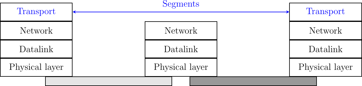
Compared to the connectionless network layer service, the transport layer service allows several applications running on a host to exchange SDUs with several other applications running on remote hosts. Let us consider two hosts, e.g., a client and a server. The network layer service allows the client to send information to the server, but if an application running on the client wants to contact a particular application running on the server, then an additional addressing mechanism is required, that is, a port. When a server application is launched on a host, it registers a port number. Clients use this port number to contact the server process.
The figure below shows a typical usage of port numbers. The client process uses port number 1234 while the server process uses port number 5678. When the client sends a request, it is identified as originating from port number 1234 on the client host and destined to port number 5678 on the server host. When the server process replies to this request, the server’s transport layer returns the reply as originating from port 5678 on the server host and destined to port 1234 on the client host.
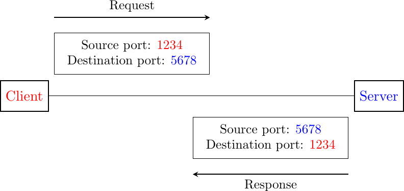
Utilization of port numbers
To support the connection-oriented service, the transport layer needs to include several mechanisms to enrich the connectionless network-layer service. The connectionless service is frequently used by users who need to exchange small SDUs. It can be easily built on top of the connectionless network layer service that we have described earlier. Users needing to either send or receive several different and potentially large SDUs, or who need structured exchanges often prefer the connection-oriented service.
User Datagram Protocol (UDP)
UDP is a widely used communication protocol for connectionless transport communication. Within an IP network, UDP does not require prior communication or a “handshake” to set up a channel or data path, and works with a minimum of protocol mechanisms. UDP does provide checksums for data integrity and port numbers for addressing different functions at the source and destination of the datagram; however, there is no guarantee of delivery, ordering, or duplicate protection.
UDP is suitable for purposes where error checking and correction are either not necessary or are performed in the application; UDP avoids the overhead of such processing. Time-sensitive applications often use UDP because dropping packets is preferable to waiting for packets delayed due to retransmission, particularly in real-time systems. The protocol was designed by David P. Reed in 1980 and formally defined in RFC 768.
UDP Datagram Structure
A UDP datagram consists of a datagram header followed by a data section (the payload data for the application). The UDP datagram header consists of 4 fields, each of which is 2 bytes (16 bits).

Ere at Norwegian Wikipedia, Public domain, via Wikimedia Commons. https://commons.wikimedia.org/wiki/File:UDP_header.png.
The UDP header fields can be explained as follows:
Source Port Number
- This field identifies the sender’s port, when used, and should be assumed to be the port to reply to if needed. If not used, it should be zero. If the source host is the client, the port number is likely to be an ephemeral port. If the source host is the server, the port number is likely to be a well-known port number from 0 to 1023.
- Destination Port Number
- This field identifies the receiver’s port and is required. Similar to a source port number, if the client is the destination host, then the port number will likely be an ephemeral port number and if the destination host is the server, then the port number will likely be a well-known port number.
- UDP Length
- This field specifies the length in bytes of the UDP header and UDP data. The minimum length is 8 bytes, the length of the header. The field size sets a theoretical limit of 65,535 bytes (8-byte header + 65,527 bytes of data) for a UDP datagram. However, the actual limit for the data length, which is imposed by the underlying IPv4 protocol, is 65,507 bytes (65,535 bytes − 8-byte UDP header − 20-byte IP header).
- Using IPv6 jumbograms, it is possible to have UDP datagrams of size greater than 65,535 bytes. RFC 2675 specifies that the length field is set to zero if the length of the UDP header plus UDP data is greater than 65,535.
- UDP Checksum
- The checksum field may be used for error-checking of the header and data. This field is optional in IPv4, and mandatory in most cases in IPv6. The field carries all-zeros if unused.
Checksum Computation
The method used to compute the checksum is defined in RFC 768, and efficient calculation is discussed in RFC 1071:
The checksum is the 16-bit one’s complement of the one’s complement sum of a pseudo header of information from the IP header, the UDP header, and the data. It is padded with zero octets at the end (if necessary) to make a multiple of two octets.
In other words, all 16-bit words are summed using one’s complement arithmetic. Add the 16-bit values up. On each addition, if a carry-out (17th bit) is produced, swing that 17th carry bit around and add it to the least significant bit of the running total. Finally, the sum is then one’s complemented to yield the value of the UDP checksum field.
If the checksum calculation results in the value zero (all 16 bits 0), it should be sent as the one’s complement (all 1s) as a zero-value checksum indicates no checksum has been calculated. In this case, any specific processing is not required at the receiver, because all 0s and all 1s are equal to zero in one’s complement arithmetic.
The differences between IPv4 and IPv6 are in the pseudo header used to compute the checksum, and that the checksum is not optional in IPv6. Under specific conditions, a UDP application using IPv6 is allowed to use a UDP zero-checksum mode with a tunnel protocol.
Reliability and Congestion Control
Lacking reliability, UDP applications may encounter some packet loss, reordering, errors, or duplication. If using UDP, the end-user applications must provide any necessary handshaking such as real-time confirmation that the message has been received. Applications such as TFTP may add rudimentary reliability mechanisms into the application layer as needed. If an application requires a high degree of reliability, a protocol such as TCP should be considered.
Stateless UDP applications are beneficial in a number of applications, however. Streaming media, real-time multiplayer games, and voice over IP (VoIP) are examples of applications that often use UDP. Real-time multimedia streaming protocols are designed to handle occasional lost packets, so only slight degradation in quality occurs, rather than large delays if lost packets were retransmitted. In these particular applications, loss of packets is not usually a fatal problem. In VoIP, for example, latency and jitter are the primary concerns. The use of TCP would cause jitter if any packets were lost as TCP does not provide subsequent data to the application while it is requesting a retransmission of the missing data.
Simple query-response protocols such as DNS, DHCP, and SMTP are suitable for UDP. UDP may also be used to model other protocols such as IP tunneling or RPCs. Because UDP supports multicast, it may be useful for service discovery (broadcast) information, such as Precision Time Protocol and Routing Information Protocol. Some VPNs such as OpenVPN may use UDP and perform error checking at the application level while implementing reliable connections.
Finally, QUIC is a transport protocol built on top of UDP. QUIC provides a reliable and secure connection using HTTP/3, which uses a combination of TCP and TLS to ensure reliability and security respectively. This means that HTTP/3 uses a single handshake to set up a connection, rather than having two separate handshakes for TCP and TLS, meaning the overall time to establish a connection is reduced.
Watch this video by Ed Harmoush for an overview of which applications are best suited for UDP.
The Connection-Oriented Service
A connection-oriented protocol is a communication protocol that establishes a reliable, dedicated connection between two devices before transmitting data. The connection ensures that data is delivered in the correct order and without any errors. The connection is maintained throughout the communication and is terminated once the communication is over. If error-correction facilities are needed at the network interface level, an application may use Transmission Control Protocol (TCP) or Stream Control Transmission Protocol (SCTP) which are designed for this purpose. We will cover TCP in this chapter.
TCP Datagram Structure
The TCP datagram header is the part of the TCP segment that contains information about the source and destination ports, sequence and acknowledgment numbers, flags, window size, checksum, and options. The TCP header has a minimum size of 20 bytes and a maximum size of 60 bytes. The TCP header format is shown below:
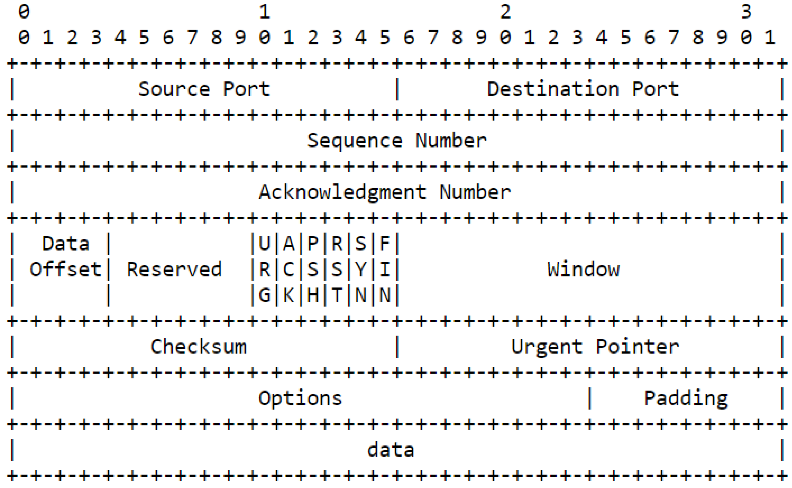
TCP header format. RFC 793—Transmission Control Protocol: https://tools.ietf.org/html/rfc793.
The TCP header fields are explained as follows:
- Source Port and Destination Port: These are 16-bit fields that identify the port numbers of the sending and receiving applications. They help to distinguish different connections between the same hosts.
- Sequence Number: This is a 32-bit field that identifies the position of the first data byte in the segment. It helps to ensure that the data is delivered in the correct order and without any gaps or duplicates.
- Acknowledgment Number: This is a 32-bit field that indicates the next expected segment from the other side. It helps to confirm that the data has been received correctly and to provide flow control.
- Header Length: This is a 4-bit field that specifies the length of the TCP header in multiples of 4 bytes. It helps to locate where the actual data begins in the segment.
- Flags: These are 6 bits that indicate the status and control of the connection. They are SYN, ACK, FIN, RST, PSH, and URG. They help to establish, maintain, and terminate the connection, as well as to indicate urgent or pushed data.
- Window Size: This is a 16-bit field that specifies how much data can be sent without receiving an acknowledgment from the other side. It helps to provide congestion control and avoid overflowing the receiver’s buffer.
- Checksum: This is a 16-bit field that contains a value calculated from the header and data fields, and helps to detect any errors or corruption in the segment.
- Options: This is a variable-length field that contains additional information or parameters for the connection. It can be up to 40 bytes long. It helps to provide enhanced functionality and performance for the connection.
Phases of the Connection-Oriented Service
An invocation of the connection-oriented service is divided into three phases.
- Connection Establishment: The first phase is the establishment of a connection, which is a temporary association between two users through a service provider. Several connections may exist at the same time between any pair of users. The sender and the receiver agree to establish a connection and exchange information about their initial sequence numbers, port numbers, and other parameters. This usually involves a three-way handshake process, where the sender sends a SYN segment, the receiver replies with a SYN-ACK segment, and the sender acknowledges with an ACK segment.
- Data Transfer: Once established, the connection is used to transfer data, or SDUs. The sender and the receiver exchange data segments, each containing a sequence number, an acknowledgment number, a checksum, and a window size. The sequence number indicates the order of the data segments, the acknowledgment number indicates the next expected segment from the other side, the checksum verifies the integrity of the data, and the window size indicates how much data can be sent without receiving an acknowledgment. Various mechanisms can be used to ensure reliable and efficient data transmission, such as retransmissions, acknowledgments, congestion control, and flow control.
- Connection Termination: This is the phase where the sender and the receiver agree to close the connection and release the resources. This phase usually involves a four-way handshake process, where the sender sends a FIN segment, the receiver replies with an ACK segment, the receiver sends its own FIN segment, and the sender acknowledges with an ACK segment. The termination can be graceful, initiated by the client, or abrupt, initiated by the server for some reason. The connection is closed after a timeout period.
An important point to note about the connection-oriented service is its reliability. A connection-oriented service can only guarantee the correct delivery of all SDUs provided that the connection has been released gracefully. This implies that while the connection is active, there is no guarantee for the actual delivery of the SDUs exchanged as the connection may need to be abruptly released at any time.
Connection Establishment
Like the connectionless service, the connection-oriented service allows several applications running on a given host to exchange data with other hosts through designated port numbers. Similarly, connection-oriented protocols use checksums/CRCs to detect transmission errors and discard segments containing an invalid checksum/CRC. An important difference between the connectionless service and the connection-oriented one is that the transport entities in the latter maintain some state during the lifetime of the connection. This state is created when a connection is established and is removed when it is released.
The three-way handshake is a fundamental process in the Transmission Control Protocol (TCP). This process is used to establish a reliable and orderly communication channel between two devices (usually computers) before they begin exchanging data.

The TCP Handshake (SnubCube): https://upload.wikimedia.org/wikipedia/commons/9/98/Tcp-handshake.svg.
The three-way handshake in TCP consists of these steps:
- SYN (Synchronize)
- One device (referred to as the “client”) intends to initiate a TCP connection with another device (referred to as the “server”).
- The client sends a TCP packet to the server with a flag set to SYN (Synchronize). This packet contains a randomly generated sequence number (SYN number) that helps in identifying and tracking this particular connection.
- SYN-ACK (Synchronize-Acknowledge)
- Upon receiving the SYN packet, the server acknowledges the client’s request by sending its own TCP packet.
- The server’s packet has the SYN flag set as well, indicating its readiness to establish a connection. It also includes an acknowledgment (ACK) of the client’s SYN number and a new randomly generated sequence number (SYN number) for itself.
- ACK (Acknowledgment)
- Finally, when the client receives the SYN-ACK packet from the server, it acknowledges the server’s response.
- The client sends a TCP packet back to the server with the ACK flag set. This packet includes the server’s SYN number as an acknowledgment.
At this point, the TCP connection is established, and both the client and server are synchronized, and can now reliably exchange data packets, knowing that the connection has been successfully established and that each party acknowledges the other’s readiness to communicate. This also helps in preventing unauthorized or forged connections, as both sides must agree on the initial sequence numbers and acknowledge each other before data transfer begins.
Data Transfer
The TCP Segment
Flow Control
Connection Release

A protocol of the transport layer in the TCP/IP protocol suite that provides an unreliable connectionless service that includes a mechanism to detect corruption in situations where TCP might be too latent, and speed is a priority. This transport layer protocol can detect corruption, but it is less reliable since it does not utilize handshaking or flow control.
"Glossary — Computer Networking : Principles, Protocols and Practice.” Available: https://beta.computer-networking.info/syllabus/default/glossary.html. Accessed: Oct. 03, 2023.
A combination of IP address and software port number used for communication between multiple processes, used to allow the transmission of information between two processes from the same machines or different machines on a network. The socket helps recognize the address of the application the data is being sent to by utilizing the IP address and port numbers.
Gupta, Trapti. “Socket Programming in Computer Network.” Scaler Topics, 19 Aug. 2022, https://www.scaler.com/topics/computer-network/socket-programming/. Accessed October 3, 2023.
Primarily responsible for maintaining top level domain names, IP address and protocol number databases. The organization also provides coordination of IPv4 and IPv6 addresses for carriers and Internet service providers. IANA does not have jurisdiction over Internet activity and does not resolve IP address conflicts.
“Definition of IANA.” PCMAG, https://www.pcmag.com/encyclopedia/term/iana. Accessed 25 Sept 2023.
Ports that are selected from a predefined range of 49152-65535. Once the tasks that are mapped to the dynamic port are completed, it is released back into the pool of ports. This helps when there are multiple connections to reduce network conflicts.
Dynamic Ports Definition - Glossary | NordVPN. 23 May 2023, https://nordvpn.com/cybersecurity/glossary/dynamic-ports/. Accessed October 2, 2023
Areas of temporary memory storage. The data is retrieved from an input before it is sent as an output, and can be placed in hardware to provide a fixed location for temporary data storage. An example of a buffer would be letting a YouTube video load by pausing it before watching it, as it creates a temporary memory of the video, causing it to load faster.
Hartleb, Franz, et al. “Network Planning and Dimensioning for Broadband Access to the Internet Regarding Quality of Service Demands:” Advances in E-Business Research, edited by In Lee, IGI Global, 2009, pp. 852–66. DOI.org (Crossref), https://doi.org/10.4018/978-1-60566-194-0.ch054. Accessed 18 Sept 2023.
A computed value that is used in error-checking or detecting that seeks to ensure the integrity of data. As it relates to transmitted data, a checksum is calculated on the data segment prior to being transmitted. Because changes to a single bit results in a completely different hash value if a bit is altered during transmission, a flag is raised.
Baeldung. CRC Vs Checksum | Baeldung on Computer Science. 16 Oct. 2020, https://www.baeldung.com/cs/crc-vs-checksum.
Refers to how much delay there is between when a signal is sent from point to a network connection. Jitter can be caused by multiple factors such as bad hardware, congestion on the network, or ping prioritization. Services like VOIP and video calls can be highly impacted by jitter.
IR Team. "Network Jitter - Common Causes and Best Solutions." Integrated Research, https://www.ir.com/guides/what-is-network-jitter. Accessed 25 Sept. 2023.
Identifies the position of the first data byte in a segment, serving as a counter of each byte sent by a host machine in TCP. The number is used to identify any data that might be missing or duplicate. It helps to also note how much data was sent or received. Gupta, Trapti. "TCP Sequence Number and Wrap Around Concept" Scaler Topics. https://www.scaler.com/topics/tcp-sequence-number. Accessed Sept. 28, 2023.
