Want to create or adapt books like this? Learn more about how Pressbooks supports open publishing practices.
7. The Network Layer II | Routing
Chapter Objectives
7-1 Summarize the functions and features of a router and routing table.
7-2 Differentiate between static and dynamic routing.
7-3 Compare distance vector and link-state routing protocols.
7-4 Explain the features of routing protocols and techniques such as RIP, OSPF, EIGRP, BGP, and MPLS.
7-5 Discuss the role of ICMP in error control.
What is Routing?
In this chapter, we are going to explore the packet delivery process, from the routing perspective. One of the main functions of routing is to determine the optimal path across a routed network for IP packets with routing tables and protocols. Some major dynamic routing protocols include the following:
Intermediate System to Intermediate System (IS-IS)
Two additional techniques are applicable to this layer:
Multiprotocol Label Switching (MPLS) is a routing technique used to improve the speed and control of network traffic
Internet Control Message Protocol (ICMP) is a network layer protocol used for diagnostics and network management.
Routers
We know that routers implement layer 3, or network layer, functions. A router’s main job is to forward packets based upon a routing table. When doing so, they also provide traffic segmentation, broadcast domains, and network subnets. Those networks are defined by router network adapters or ports to which IP addresses are assigned. Those IP addresses are typically the default gateway to PCs and servers or other networking devices.
Routers also connect to service providers and act as gateways to other networks, typically found at the perimeter or edge of the network. Some of those network adapters will be other than Ethernet. They will have connectivity to serial interfaces, DSL connections, and other forms of wide area networks (WANs). The main components are similar to those of any computing and network device: CPU, motherboard, RAM, and ROM. In fact, routers have different types of memory. They also have flash, where the image of the operating system resides. These computing resources are now so powerful that they allow routers to start behaving like other network elements; they can incorporate firewall functions and even voice routing capabilities for IP telephony environments. This means that routers today act as traditional layer 3 devices, but are also the jack of all trades. Therefore, we can integrate multiple functions within our network via software upgrades and via network modules in configuration routers.
Watch this CertBros video to learn about the difference between a modem and a router.
Routing in IP Networks
To determine the routes of network traffic, we build a map of the network. For this, routers typically use either static routing or dynamic routing protocols.
Static routing is a method of configuring routes manually on each router in the network. Static routes do not change unless the network administrator updates them. Static routing is only suitable for small and stable networks that do not require frequent updates.
Dynamic routing is a method of automatically learning and updating routes from neighboring routers using routing protocols such as the ones mentioned in the introduction. Dynamic routes change according to the network topology and conditions. Dynamic routing provides more scalability and adaptability than static routing, but it also consumes more bandwidth and resources.
During the process of path determination, routers will consider multiple alternatives to get to the same place; those alternatives result from the redundancy built into most network designs. We want multiple paths, so that if one goes down, other alternatives will become available. In determining the best path, routers will consider several factors.
One is the source of the information, and so, you might have multiple dynamic routing protocols or even static routing populating the routing table to indicate options to the router. The second piece of information is the cost of taking each path, acknowledging that the path is made up of multiple links or hops that are defined by other routers. We can add the concept of the cost in the context of the total path, which is nothing more than the sum of all the costs to reach each hop in the path.
The two decisions are ruled by different pieces of information. For example, in order to define a tie breaker between sources of information, the routers use the administrative distance. If a routing protocol such as OSPF informs the router about a destination and RIP is also informing that router about the same destination, then the administrative distance will define who wins. Once the source is selected, then the cost is what matters; in other words, if OSPF provides the information on those two paths, then the cost of the path will define which one is taken. This is similar to having two maps to drive from one city to the other. You first select which map you are going to follow and then if the map is giving you more than one option, then you will select the option according to perhaps the amount of time it takes or the amount of miles you have to drive for each option.
Routing Tables
The routing table contains the network layer intelligence that tells the router how to forward packets to remote destinations. Initially, that routing table is made up of networks that are directly connected to the particular router. After that, information about remote destinations is obtained by either populating the routing table with static routes explicitly set by an administrator or by populating the routing table via routing table advertisements from other routers.
Routers will share information that allows other routers to know about all the “gossip” in the network. In both cases, static and dynamic routing notice how routers use the reserved subnet addresses or network addresses that contain all 0s in the host portion of the IP address.
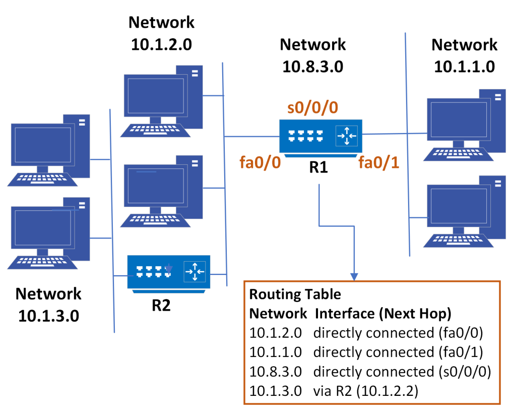
Suppose we are working with a classless subnetted class A address. Network 10 is split into subnets similar to a class C. However, the host portion of the address, the fourth byte is all 0s and that represents that subnet or network itself. In other words, these are destination networks or subnets. With remote destinations, the routing table entries show what the next hop is in order to reach that destination. So, in order to reach 10.1.3.0, our next-hop is router 2 at 10.1.2.2.
Figure 5-1: A Class A subnetted network and its routing table
These are categories of routing table entries that could be populated either dynamically or statically. Some of them are born with the router. As soon as the router boots up, it will identify its directly connected and active networks and interfaces and define them as reachable destinations, only because of the fact that the router is directly attached or connected to it. Even smarter is the fact that the routers will communicate with each other, exchange routing information via dynamic routing protocols like OSPF or EIGRP, and then learn not only about those destinations, but also adjust to changes on those destinations.
Routing protocols will be able to identify topology changes and inform each other about them. Soon enough, entries will appear and disappear from the routing table according to availability; again, an administrator could come in and manually insert static entries. This is sometimes not recommended because they will be static and therefore will not adjust to network changes. In other words, if the entry or the destination goes down, the entry will remain there and the router will still forward packets to a destination that is not available. Perhaps a special case of a static route is the default route. Although they can also be learned dynamically, static defaults are used when no explicit route to a destination is known and so this is the entry that identifies all unknown destinations. The router will say, “If I do not know about a certain destination, I will forward a packet to someone that does, typically another router.”
See a sample routing table in action in this Network Direction video.
Routing Metrics
Optimal path selection depends on what is known as the cost to reach a destination across a certain path. Again, the cost of a path is made up of incremental costs for each hop along the path. The cost is also known as a metric. Different routing protocols will consider different criteria in order to define the metric. Older technologies and protocols consider the number of routers along the path in order to reach a destination; this is called the hop count. Hop count is sometimes not an efficient way to determine cost, because you could have different bandwidths associated with each hop or each link.
Some routing protocols consider bandwidth and other parameters as a measure of cost. For example, EIGRP considers bandwidth delay, reliability, load, andmaximum transmission unit. In that case, a path with enough bandwidth, but one that is fully congested, would not be selected and perhaps another path with less available bandwidth would be selected because it is less congested and more reliable.
This section is adapted from “IP Network Addressing Scheme | Class A B C Subnets.” Learncisco.Net, https://www.learncisco.net/courses/icnd-1/lan-connections/network-addressing-scheme.html. Accessed 16 Sept. 2023. Except where otherwise noted, content on this site is licensed under a Creative Commons Attribution 4.0 International license.
Concepts Corner
What is ICMP?
The Internet Control Message Protocol (ICMP) is a network layer protocol used for diagnostics and network management. Because IP does not have an inbuilt mechanism for sending error and control messages, it relies on ICMP to provide error control. ICMP messages communicate information about network connectivity issues back to the source of the compromised transmission.
Some Key Functions of ICMP:
Error Reporting: ICMP is used to report errors in the processing of IP packets. For example, if a router can’t deliver a packet, it sends an ICMP message back to the source.
Network Diagnostics: Tools like ping and traceroute use ICMP to diagnose network issues. Ping sends ICMP Echo Request messages to a destination and listens for Echo Reply messages to check connectivity.
Flow Control: ICMP can help manage the flow of data to prevent network congestion. For instance, if a router is overwhelmed, it can send an ICMP Source Quench message to slow down the sender.
Some Common ICMP Messages:
Echo Request and Echo Reply: Used by the ping command to test connectivity.
Destination Unreachable: Indicates that a packet couldn’t reach its destination.
Time Exceeded: Sent when a packet’s Time to Live (TTL) expires, often used by traceroute.
Redirect: Informs a host to use a different route for sending packets.
Routing protocol selection, if you are doing dynamic routing, is key in determining the cost or metric and, therefore, how efficient and optimal the path selection will be. Another factor is the convergence time, which is defined by the time it takes for routing protocol to detect a topology change and adjust by selecting an alternative path if the main path is down. Different categories of routing protocols using dynamic routing define their approach to costs and metrics, and their behavior under those circumstances.
Distance Vector and Link-State Routing Protocols
Using the distance vector protocol, routers do not need to know the whole path toward the destination. They only need to know the direction or vector in which to send a packet. In that sense, it will only keep information in the routing tables related to what the next-hop should be in order to reach a certain destination.
Distance vector protocols suffer from many disadvantages. One of these is that they periodically advertise the routing tables. Some of them use broadcasts to advertise the entire routing table. This creates too much, potentially unnecessary, overhead in the network if the network changes infrequently. A similar example would be frequently calling everybody to tell them about the same gossip over and over again. RIP, or Routing Information Protocol, is an example of a distance vector protocol. RIP uses a hop count as the measure of cost.
A link-state protocol is more efficient and effective in creating network topologies, sharing them, and selecting the best path as compared to distance vector protocols. There are several differences between the two categories. For example, link-state protocols will not broadcast the information from each router, but instead, use multicast to advertise the known links to each router’s neighbor. Secondly, link-state protocols do not advertise periodically. After an initial flood of information, only changes to the topology are advertised. In other words, if the link goes down then that small change will be advertised via multicast. Thirdly, a router does not only know about the next hop toward a destination; it knows the whole topological map of the network. Each router after the initial flood will build that map of the network, which includes all the routers and all the links. With that information, each router is capable of browsing those tables via the shortest path first algorithm, and selecting the best path toward each destination. This would be installed in a routing table. So, a chain reaction of events for each router is not needed to make a topological change and adjust routing decisions.
Once there is a change, a link going down, for example, only a little branch of the tree will be affected and only that change is advertised to the network. These smaller, more selective changes are called incremental updates. All of these features make link-state protocols more effective and efficient in dealing with network changes.
IGP and EGP Protocol Classes
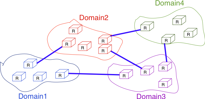
In a large IP network such as the global Internet, routers need to exchange routing information. The Internet is an interconnection of networks, often called domains, that are under different responsibilities. The Internet is composed of more than tens of thousands of different domains, with the number constantly growing. A domain can be a small enterprise that manages a few routers in a single building, a larger enterprise with a hundred routers at multiple locations, or a large Internet Service Provider (ISP) managing thousands of routers. Two classes of routing protocols are used to allow these domains to efficiently exchange routing information.
Figure 5-2: Organization of a small Internet
The first class of these routing protocols are the intradomain routing protocols (sometimes also called the interior gateway protocols or IGP). An intradomain routing protocol is used by all routers inside a domain to exchange routing information about the destinations that are reachable inside the domain. There are several intradomain routing protocols. Some domains use RIP, which is a distance vector protocol. Other domains use link-state routing protocols such as OSPF or IS-IS. Finally, some domains use static routing or proprietary protocols such as IGRP or EIGRP.
These intradomain routing protocols usually have two objectives. First, they distribute routing information that corresponds to the shortest path between two routers in the domain. Second, they should allow the routers to quickly recover from link and router failures.
The second class of routing protocols are the interdomain routing protocols (sometimes also called the exterior gateway protocols or EGP). The objective of an interdomain routing protocol is to distribute routing information between domains. For scalability reasons, an interdomain routing protocol must distribute aggregated routing information and considers each domain as a black box.
A very important difference between intradomain and interdomain routing are the routing policies that are used by each domain. Inside a single domain all routers are considered equal. When several routes are available to reach a given destination prefix, the best route is selected based on technical criteria. Such criteria includes the route with the shortest delay, the route with the minimum number of hops or the route with the highest bandwidth.
When we consider the interconnection of domains that are managed by different organizations, this is no longer true. Each domain implements its own routing policy. A routing policy is composed of three elements : an import filter that specifies which routes can be accepted by a domain, an export filter that specifies which routes can be advertised by a domain and a ranking algorithm[/pb_glossary] that selects the best route when a domain knows several routes towards the same destination prefix. As we will see later, another important difference is that the objective of the interdomain routing protocol is to find the cheapestroute towards each destination. There is only one interdomain routing protocol : BGP.
Intradomain Routing: RIP and OSPF
In this section, we briefly describe the key features of the two main intradomain unicast routing protocols: RIP and OSPF.
RIP
The Routing Information Protocol (RIP) is the simplest routing protocol that was standardized for the TCP/IP protocol suite. RIP is defined in RFC 2453.
RIP routers periodically exchange RIP messages. The format of these messages is shown below. A RIP message is sent inside a UDP segment whose destination port is set to 521. A RIP message contains several fields. The command field indicates whether the RIP message is a request or a response. When a router boots, its routing table is empty and it cannot forward any packet. To speed up the discovery of the network, it can send a request message to the RIP IPv6 multicast address, FF02::9. All RIP routers listen to this multicast address and any router attached to the subnet will reply by sending its own routing table as a sequence of RIP messages. In steady state, routers multicast one or more RIP response messages every 30 seconds. These messages contain the distance vectors that summarize the router’s routing table. The current version of RIP is version 2, defined in RFC 2453 for IPv4 and RFC 2080 for IPv6.
Figure 5-3: The RIP message format
Each RIP message contains a set of route entries. Each route entry is encoded as a 20-byte field whose format is shown below. RIP was initially designed to be suitable for different network layer protocols. Some implementations of RIP were used in XNS or IPX networks RFC 2453. The format of the route entries used by RFC 2080 is shown below. Prefix length is the length of the subnet identifier in bits and the metric is one byte. The maximum metric supported by RIP is 15.
Figure 5-4: Format of the RIP IPv6 route entries
A Note on RIP Timers
The first RIP implementations sent their distance vector exactly every 30 seconds. This worked well in most networks, but some researchers noticed that routers were sometimes overloaded because they were processing too many distance vectors at the same time [FJ1994]. They collected packet traces in these networks and found that after some time, the routers’ timers became synchronized, i.e., almost all routers were sending their distance vectors at almost the same time. This synchronization of the transmission times of the distance vectors caused an overload on the routers’ CPU and also increased the convergence time of the protocol in some cases. This was mainly due to the fact that all routers set their timers to the same expiration time after having processed the received distance vectors. Sally Floyd and Van Jacobson proposed in [FJ1994] a simple solution to solve this synchronization problem. Instead of advertising their distance vector exactly after 30 seconds, a router should send its next distance vector after a delay chosen randomly in the [15,45] intervalRFC 2080. This randomization of the delays prevents the synchronization that occurs with a fixed delay and is now a recommended practice for protocol designers.
OSPF
Link-state routing protocols are used in IP networks. Open Shortest Path First(OSPF), defined in RFC 2328, is the link state routing protocol that has been standardized by the IETF. The last version of OSPF, which supports IPv6, is defined in RFC 5340. OSPF is frequently used in enterprise networks and in some ISP networks. However, ISP networks often use the IS-IS link-state routing protocol [ISO10589] , which was developed for the ISO CLNP protocol but was adapted to be used in IP RFC 1195 networks before the finalization of the standardization of OSPF.
Compared to the basics of link-state routing protocols, there are some particularities of OSPF that are worth discussing. We will discuss one in this section as an example.
In a large network, flooding the information about all routers and links to thousands of routers or more may be costly as each router needs to store all the information about the entire network. A better approach would be to introduce hierarchical routing. Hierarchical routing divides the network into regions. All the routers inside a region have detailed information about the topology of the region but only learn aggregated information about the topology of the other regions and their interconnections. OSPF supports a restricted variant of hierarchical routing. In OSPF’s terminology, a region is called an area.
OSPF imposes restrictions on how a network can be divided into areas. An area is a set of routers and links that are grouped together. Usually, the topology of an area is chosen so that a packet sent by one router inside the area can reach any other router in the area without leaving the area . An OSPF area contains two types of routers in RFC 2328:
Internal router: A router whose directly connected networks belong to the area
Area border router: A router that is attached to several areas
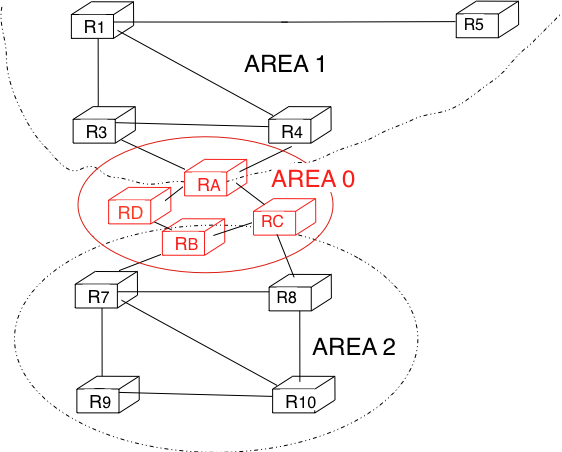
For example, the network shown in the figure below has been divided into three areas : area 0, containing routers RA, RB, RC and RD; area 1, containing routers R1, R3, R4, R5 and RA; and area 2 containing R7, R8, R9, R10, RB and RC. OSPF areas are identified by a 32-bit integer, which is sometimes represented as an IP address. Among the OSPF areas, area 0, also called the backbone area, has a special role. The backbone area groups all the area border routers (routers RA, RB and RC in the figure below) and the routers that are directly connected to the backbone routers but do not belong to another area (router RD in the figure below). An important restriction imposed by OSPF is that the path between two routers that belong to two different areas (e.g., R1 and R8 in the figure below) must pass through the backbone area.
Figure 5-5: OSPF areas
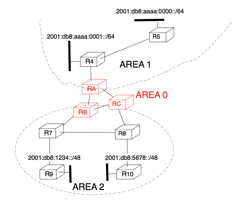
Inside each non-backbone area, routers distribute the topology of the area by exchanging link state packets with the other routers in the area. The internal routers do not know the topology of other areas, but each router knows how to reach the backbone area. Inside an area, the routers only exchange link-state packets for all destinations that are reachable inside the area. In OSPF, the inter-area routing is done by exchanging distance vectors. This is illustrated by the network topology shown below.
Figure 5-6: Hierarchical routing with OSPF
Let us first consider OSPF routing inside area 2. All routers in the area learn a route towards 2001:db8:1234::/48 and 2001:db8:5678::/48. The two area border routers, RB and RC, create network summary advertisements. Assuming that all links have a unit link metric, these would be:
RB advertises 2001:db8:1234::/48 at a distance of 2 and 2001:db8:5678::/48 at a distance of 3
RC advertises 2001:db8:5678::/48 at a distance of 2 and 2001:db8:1234::/48 at a distance of 3
These summary advertisements are flooded through the backbone area attached to routers RB and RC. In its routing table, router RA selects the summary advertised by RB to reach 2001:db8:1234::/48 and the summary advertised by RC to reach 2001:db8:5678::/48. Inside area 1, router RA advertises a summary indicating that 2001:db8:1234::/48 and 2001:db8:5678::/48 are both at a distance of 3 from itself.
On the other hand, consider the prefixes 2001:db8:aaaa:0000::/64 and 2001:db8:aaaa:0001::/64 that are inside area 1. Router RA is the only area border router that is attached to this area. This router can create two different network summary advertisements :
2001:db8:aaaa:0001::/64 at a distance of 1 from RA
2001:db8:aaaa:0000::/64 at a distance of 2 from RA
The first summary advertisement provides precise information about the distance used to reach each prefix. However, all routers in the network have to maintain a route towards 2001:db8:aaaa:0000::/64 and a route towards 2001:db8:aaaa:0001::/64 that are both via router RA. The second advertisement would improve the scalability of OSPF by reducing the number of routes that are advertised across area boundaries. However, in practice this requires manual configuration on the border routers.
See Kevin Barker’s overview of OSPF below for an overview of this protocol.
EIGRP
The Enhanced Interior Gateway Routing Protocol(EIGRP) is an advanced distance-vector routing protocol that is used on a computer network for automating routing decisions and configuration. It was designed by Cisco Systems as a proprietary protocol, available only on Cisco routers.
EIGRP only sends incremental updates, reducing the routers’ workload and the amount of information transmitted. RIP and OSPF send periodic updates, which consume more bandwidth and CPU resources.
EIGRP supports variable-length subnet masking (VLSM) and classless inter-domain routing (CIDR), which allow for more efficient use of IP addresses and network design. RIP only supports fixed-length subnet masking (FLSM) and classful routing, which limit the scalability and flexibility of the network.
EIGRP uses the diffusing update algorithm (DUAL) to calculate the shortest path to a destination within a network. DUAL ensures fast convergence and loop-free routing. RIP uses the hop count as the metric, which can cause slow convergence and routing loops. OSPF uses the link-state algorithm, which requires more memory and processing power than DUAL.
EIGRP supports unequal-cost load balancing, which allows for optimal utilization of multiple paths to a destination. RIP and OSPF only support equal-cost load balancing, which can result in underutilized or congested links.
Interdomain Routing: BGP
The Internet uses a single interdomain routing protocol: the Border Gateway Protocol. We will describe it briefly here. The current version of BGP is defined in RFC 4271. BGP differs from the intradomain routing protocols that we have already discussed in several ways. First, BGP is a path-vector protocol. When a BGP router advertises a route towards a prefix, it announces the IP prefix and the interdomain path used to reach this prefix. From BGP’s point of view, each domain is identified by a unique autonomous system (AS) number and the interdomain path contains the AS numbers of the transit domains that are used to reach the associated prefix. This interdomain path is called the AS Path. Thanks to these AS-Paths, BGP does not suffer from the count-to-infinity problems that affect distance vector routing protocols. Furthermore, the AS-Path can be used to implement some routing policies. Another difference between BGP and the intradomain routing protocols is that a BGP router does not send the entire contents of its routing table to its neighbors regularly. Given the size of the global Internet, routers would be overloaded by the number of BGP messages that they would need to process. BGP uses incremental updates, i.e., it only announces the routes that have changed to its neighbors.
The figure below shows a simple example of the BGP routes that are exchanged between domains. In this example, prefix 2001:db8:1234/48 is announced by AS1. AS1 advertises a BGP route towards this prefix to AS2. The AS-Path of this route indicates that AS1 is the originator of the prefix. When AS4 receives the BGP route from AS1, it re-announces it to AS2 and adds its AS number to the AS-Path. AS2 has learned two routes towards prefix 2001:db8:1234/48. It compares the two routes and prefers the route learned from AS4 based on its own ranking algorithm. AS2 advertises to AS5 a route towards 2001:db8:1234/48 with its AS-Path set to AS2:AS4:AS1. Thanks to the AS-Path, AS5 knows that if it sends a packet towards 2001:db8:1234/48 the packet first passes through AS2, then through AS4 before reaching its destination inside AS1.
Figure 5-7: Simple exchange of BGP routes
BGP routers exchange routes over BGP sessions. A BGP session is established between two routers belonging to two different domains that are directly connected. As explained earlier, the physical connection between the two routers can be implemented as a private peering link or over an Internet eXchange Point. A BGP session between two adjacent routers runs above a TCP connection (the default BGP port is 179). In contrast with intradomain routing protocols that exchange IP packets or UDP segments, BGP runs above TCP because TCP ensures a reliable delivery of the BGP messages sent by each router without forcing the routers to implement acknowledgements, checksums, etc. Furthermore, the two routers consider the peering link to be up as long as the BGP session and the underlying TCP connection remain up. The two endpoints of a BGP session are called BGP peers.
In practice, to establish a BGP session between routers R1 and R2 in the figure above, the network administrator of AS3 must first configure on R1 the IP address of R2 on the R1-R2 link and the AS number of R2. Router R1 then regularly tries to establish the BGP session with R2. R2 only agrees to establish the BGP session with R1 once it has been configured with the IP address of R1 and its AS number. For security reasons, a router never establishes a BGP session that has not been manually configured on the router.
The BGP protocol RFC 4271 defines several types of messages that can be exchanged over a BGP session :
OPEN: this message is sent as soon as the TCP connection between the two routers has been established. It initializes the BGP session and allows the negotiation of some options. Details about this message may be found in RFC 4271
NOTIFICATION: this message is used to terminate a BGP session, usually because an error has been detected by the BGP peer. A router that sends or receives a NOTIFICATION message immediately shutdowns the corresponding BGP session.
UPDATE: this message is used to advertise new or modified routes or to withdraw previously advertised routes.
KEEPALIVE: this message is used to ensure a regular exchange of messages on the BGP session, even when no route changes.
When a BGP router has not sent an UPDATE message during the last 30 seconds, it shall send a KEEPALIVE message to confirm to the other peer that it is still up. If a peer does not receive any BGP message during a period of 90 seconds, the BGP session is considered to be down and all the routes learned over this session are withdrawn.
As explained earlier, BGP relies on incremental updates. This implies that when a BGP session starts, each router first sends BGP UPDATE messages to advertise to the other peer all the exportable routes that it knows. Once all these routes have been advertised, the BGP router only sends BGP UPDATE messages about a prefix if the route is new, one of its attributes has changed, or the route became unreachable and must be withdrawn. The BGP UPDATE message allows BGP routers to efficiently exchange such information while minimizing the number of bytes exchanged. Each UPDATE message contains:
a list of IP prefixes that are withdrawn
a list of IP prefixes that are (re-)advertised
the set of attributes (e.g., AS-Path) associated to the advertised prefixes
Watch this video from Keith Barker with a short overview of how traffic is routed on the Internet!
Discussion Topics
Multiprotocol Label Switching (MPLS) is a layer 3 networking technology that directs data from one node to the next based on labels rather than network addresses.Unlike other network protocols that route traffic based on source and destination address, MPLS routes traffic based on predetermined labels. MPLS can encapsulate packets of various network protocols, hence the multiprotocol component of the name. MPLS works in a virtual private network (VPN) and integrates with any underlying infrastructure, making it a scalable, low latency networking option. However, as data moved into the cloud, MPLS may not be efficient or cost-effective.
Read about how some organizations are moving from MPLS to SDWan: “What is the Difference Between SD-WAN and MPLS?,” Palo Alto Networks. Available: https://www.paloaltonetworks.com/cyberpedia/sd-wan-vs-mpls.
Then consider these questions.
What are the security implications of moving from MPLS to SD-WAN?
How does the flexibility and scalability of SD-WAN influence its adoption over MPLS in modern enterprises?
How do MPLS and SD-WAN handle network congestion and traffic prioritization differently?
We have explored the approaches that the network layer takes to addressing, subnetting and routing. Next, we’ll look at the next layer, the transport layer wraps around the network layer by providing services that enhance the reliability and functionality of data transmission across the network!
[42] S. Floyd and V. Jacobson, “The synchronization of periodic routing messages,” IEEE/ACM Transactions on Networking, vol. 2, no. 2, pp. 122–136, Apr. 1994, doi: 10.1109/90.298431. Available: https://ieeexplore.ieee.org/document/298431
Do you have any comments (errors, suggestions, etc.) about this section? Please ping us by clicking on the link below and sharing your feedback/suggestions. Thank you!