Want to create or adapt books like this? Learn more about how Pressbooks supports open publishing practices.
4. The Physical Layer
Chapter Objectives
4-1 Identify various types of physical media used to exchange information in computer networks.
4-2 Summarize the principles of the physical transmission of data.
4-3 Define the processes that facilitate the primary types of modulation.
4-4 Differentiate between hubs, repeaters, switches, bridges, and routers.
4-5 Describe the role of a network interface card (NIC), media converters, and firewalls in networks.
Connecting Hosts Through Physical Media
The first step when building a network, even a worldwide network such as the Internet, is to connect two hosts together. To enable the two hosts to exchange information, they need to be linked together by some kind of physical media. Various types of physical media can be used to exchange information. A few of these are listed below.
Electrical Cable. Information can be transmitted over different types of electrical cables. The most common ones are the twisted pair cable (that are used in the telephone network, but also in enterprise networks) and coaxial cable (that are still used in cable TV networks, but are no longer used in enterprise networks). Some networking technologies operate over the classical electrical cable.
Optical Fiber. Optical fiber is frequently used in public and enterprise networks when the distance between the communication devices is larger than one kilometer. There are two main types of optical fiber: multi-mode and single-mode. Multi-mode is much cheaper than single-mode fiber because a LED can be used to send a signal over a multi-mode fiber while a single-mode fiber must be driven by a laser. Due to the different modes of propagation of light, multi-mode fibers are limited to distances of a few kilometers while single-mode fibers can be used over distances greater than several tens of kilometers. In both cases, repeaters can be used to regenerate the optical signal at one endpoint of a fiber to send it over another fiber.
Wireless. In this case, a radio signal is used to encode the information exchanged between the communicating devices. Many types of modulation techniques are used to send information over a wireless channel and there is lot of innovation in this field with new techniques appearing every year. While most wireless networks rely on radio signals, increasingly some are using a laser that sends light pulses to a remote detector. These optical techniques create point-to-point links while radio-based techniques can be used to build networks containing devices spread over a small geographical area.
These physical media can be used to exchange information once this information has been converted into a suitable electrical signal. Entire telecommunication courses and textbooks are devoted to the problem of converting analog or digital information into an electrical signal so that it can be transmitted over a given physical link. In this text, we only consider two very simple schemes that allow to transmit information over an electrical cable. This enables us to highlight the key problems when transmitting information over a physical link. We are only interested in techniques that allow transmitting digital information through the wire. Here, we will focus on the transmission of bits, i.e., either 0 or 1.
For an overview of physical cables and when to use each, watch this Lawrence Systems video [22]!
Bit Rates
In computer networks, the bit rate of the physical layer is always expressed in bits per second. One Mbps is one million bits per second and one Gbps is one billion bits per second. This is in contrast with memory specifications that are usually expressed in bytes (8 bits), kilobytes (1024 bytes) or megabytes (1048576 bytes). Transferring one MByte through a 1 Mbps link lasts 8.39 seconds.
To illustrate some of the principles behind the physical transmission of information, let us consider the simple case of an electrical wire that is used to transmit bits. Assume that the two communicating hosts want to transmit one thousand bits per second. To transmit these bits, the two hosts can agree on the following rules :
On the sender side :
Set the voltage on the electrical wire at +5V during one millisecond to transmit a bit set to 1.
Set the voltage on the electrical wire at -5V during one millisecond to transmit a bit set to 0.
On the receiver side :
Every millisecond, record the voltage applied on the electrical wire. If the voltage is set to +5V, record the reception of bit 1.
Otherwise, record the reception of bit 0.
This transmission scheme has been used in some early networks. We use it as a basis to understand how hosts communicate. From our viewpoint, dealing with voltages is unusual. We can rely on models that enable them to reason about the issues that they face without having to consider all implementation details. The physical transmission scheme described above can be represented with a time-sequence diagram.
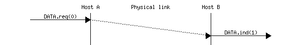
A time-sequence diagram describes the interactions between communicating hosts. By convention, the communicating hosts are represented in the left and right parts of the diagram while the electrical link occupies the middle of the diagram. In such a time-sequence diagram, time flows from the top to the bottom of the diagram. The transmission of one bit of information is represented by three arrows. Starting from the left, the first horizontal arrow represents the request to transmit one bit of information. This request is represented by a primitive, which can be considered as a kind of procedure call. This primitive has one parameter (the bit being transmitted) and a name (data.request in this example). By convention, all primitives that are named something.request correspond to a request to transmit some information. The dashed arrow indicates the transmission of the corresponding electrical signal on the wire. Electrical and optical signals do not travel instantaneously. The diagonal dashed arrow indicates that it takes some time for the electrical signal to be transmitted from Host A to Host B. Upon reception of the electrical signal, the electronics on Host B’s network interface detects the voltage and converts it into a bit. This bit is delivered as a data.indication primitive. The dashed lines also represents the relationship between two (or more) primitives. Such a time-sequence diagram provides information about the ordering of the different primitives, but the distance between two primitives does not represent a precise amount of time.
Figure 2-1: A time-sequence diagram illustrating a correct transmission of a bit over the physical layer
Time-sequence diagrams are useful when trying to understand the characteristics of a given communication scheme. When considering the above transmission scheme, it is useful to evaluate whether this scheme allows the two communicating hosts to reliably exchange information. A digital transmission is considered as reliable when a sequence of bits that is transmitted by a host is received correctly at the other end of the wire. In practice, achieving perfect reliability when transmitting information using the above scheme is difficult.
Several problems can occur with such a transmission scheme. The first problem is that electrical transmission can be affected by electromagnetic interference. Interference can have various sources including natural phenomena (e.g., thunderstorms, variations of the magnetic field, etc.) but also other electrical signals (such as interference from neighboring cables, interference from neighboring antennas, etc.) Due to these various types of interference, there is, unfortunately, no guarantee that when a host transmits one bit on a wire, the same bit is received at the other end. This is illustrated in the figure below where a data.request(0) on the left host leads to a data.indication(1) on the right host.
Figure 2-2: A time-sequence diagram illustrating an incorrect transmission of a bit over the physical layer
With the above transmission scheme, a bit is transmitted by setting the voltage on the electrical cable to a specific value during some period of time. We have seen that due to electromagnetic interference, the voltage measured by the receiver can differ from the voltage set by the transmitter. This is the main cause of transmission errors. However, this is not the only type of problem that can occur.
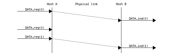
Besides defining the voltages for bits 0 and 1, the above transmission scheme also specifies the duration of each bit. If one million bits are sent every second, then each bit lasts 1 microsecond. On each host, the transmission (and the reception) of each bit is triggered by a local clock having a 1 MHz frequency. These clocks are the second source of problems when transmitting bits over a wire. Although the two clocks have the same specification, they run on different hosts, possibly at a different temperature and with a different source of energy. In practice, it is possible that the two clocks do not operate at exactly the same frequency. Assume that the clock of the transmitting host operates at exactly 1000000 Hz while the receiving clock operates at 999999 Hz. This is a very small difference between the two clocks. However, when using the clock to transmit bits, this difference is important. With its 1000000 Hz clock, the transmitting host will generate one million bits during a period of one second. During the same period, the receiving host will sense the wire 999999 times and thus will receive one bit less than the bits originally transmitted. This small difference in clock frequencies implies that bits can “disappear” during their transmission on an electrical cable. This is illustrated in the figure below.
Figure 2-3: A time-sequence diagram illustrating a “disappearing” bit in a transmission over the physical layer
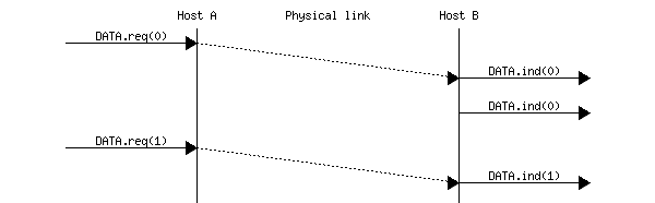
A similar reasoning applies when the clock of the sending host is slower than the clock of the receiving host. In this case, the receiver will sense more bits than the bits that have been transmitted by the sender. This is illustrated in the figure below where the second bit received on the right was not transmitted by the left host.
Figure 2-4: A time-sequence diagram illustrating an extra bit in a transmission over the physical layer
The physical transmission of information through a wire is often considered a black box that allows for the transmission of bits. This black box is commonly referred to as the physical layer service and is represented by using the data.request and data.indication primitives introduced earlier. This physical layer service facilitates the sending and receiving of bits, by abstracting the technological details that are involved in the actual transmission of the bits as an electromagnetic signal. However, it is important to remember that the physical layer service is imperfect and has the following characteristics:
The physical layer service may change, e.g., due to electromagnetic interference, the value of a bit being transmitted
The physical layer service may deliver fewer bits to the receiver than the bits sent by the sender
The physical layer service may deliver more bits to the receiver than the bits sent by the sender
Encoding and Modulation
Data encoding and modulation are interconnected processes used in computer networks to transmit information efficiently and reliably over communication channels. They are essential for converting digital data into analog signals that can be transmitted over various physical mediums, such as cables, fiber optics, or wireless channels. While they serve different purposes, they are closely related and often used together in practical communication systems.
Encoding is the process of converting digital or analog information into a specific format suitable for transmission. It involves transforming the original data into a signal that can be easily transmitted over a communication channel. Data encoding involves representing digital data as a series of symbols or bits, which can then be transmitted over a communication channel. The primary goal of encoding is to ensure that the transmitted signal can be accurately received and interpreted by the receiving device.
Digital encoding at the physical layer is the process of converting digital data (binary 1s and 0s) into signals that can be transmitted over a physical medium. This conversion is necessary because raw binary data cannot be directly sent over most communication channels and must be encoded into a specific waveform. For example, in copper cable networks, encoding converts binary data into electrical pulses. In fiber optic networks, it transforms data into light patterns, and in wireless networks, it creates specific radio wave patterns.
These different encoding methods are used depending on the physical medium:
Electrical signals: Manchester encoding, Non-Return-to-Zero (NRZ)
Digital encoding provides benefits in terms of error control, signal processing capabilities, and robustness against noise, making it increasingly prevalent in modern telecommunications systems.
Analog encoding, on the other hand, involves transmitting data as continuous signals that vary in amplitude, frequency, or phase. Analog signals vary continuously, representing information as a smooth, unbroken wave. Analog encoding is often better suited for representing natural phenomena like sound or light, as it can capture subtle variations more precisely. Analog encoding often uses modulation to transmit digital data, which modifies a carrier signal’s properties, such as amplitude, frequency, or phase, to carry the information from the source to the destination. Modulation allows the information signal to be transmitted efficiently over long distances without significant loss or interference. The modulated signal can then be demodulated at the receiver to recover the original digital data.
There are various modulation techniques:
Amplitude modulation (AM): In AM, the amplitude of the carrier signal is varied in proportion to the amplitude of the modulating signal. This variation carries the information.
Frequency modulation (FM): In FM, the frequency of the carrier signal is varied based on the amplitude of the modulating signal. Changes in frequency represent the information.
Phase modulation (PM): In PM, the phase of the carrier signal is changed in response to the input signal. Phase shifts correspond to the transmitted data.
In digital communication, encoding is often done before modulation. For instance, in a digital radio transmission, the original digital data might first undergo encoding (e.g., using error-correcting codes), and then the encoded data is modulated onto a carrier signal for transmission. These techniques help ensure that the transmitted data can be accurately received despite potential noise and interference in the communication channel. The choice of encoding and modulation techniques depends on factors such as the channel characteristics, data rate, and noise level.
What are some factors that impact the efficiency and accuracy of data transmission?
Bandwidth: The range of frequencies available for data transmission. Higher bandwidth allows for higher data transfer rates, improving efficiency.
Signal-to-Noise Ratio (SNR): The ratio of the signal power to the noise power. A higher SNR means clearer signals and fewer errors, enhancing accuracy.
Latency: The time it takes for a signal to travel from the sender to the receiver. Lower latency results in faster communication, which is crucial for real-time applications.
Error Rate: The rate at which errors occur in the transmitted data. Lower error rates mean more accurate data transmission, reducing the need for retransmissions.
Synchronization: The alignment of the sender and receiver clocks. Proper synchronization ensures that data is correctly interpreted by the receiver.
Interference: External signals that disrupt the transmission. Minimizing interference through shielding and proper channel selection improves transmission quality.
Attenuation: The reduction in signal strength as it travels through a transmission medium. With higher attenuation, the signal becomes weaker over distance, which can lead to data loss or the need for signal amplification. The signal can be boosted using repeaters or amplifiers, choosing higher quality cables, and minimizing interference.
Transmission Medium: Copper wires, fiber optics, wireless media, etc. Different media have varying capacities, noise levels, and susceptibilities to interference.
Encoding Schemes: Manchester encoding, NRZ (Non-Return-to-Zero), 4B/5B encoding. Proper encoding schemes help in reducing errors and improving signal integrity.
Modulation Techniques: Amplitude modulation (AM), frequency modulation (FM), phase modulation (PM). Effective modulation techniques can enhance the robustness and efficiency of data transmission.
Example: Manchester Encoding
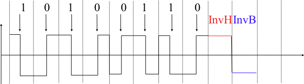
Many types of encodings have been defined to transmit information over an electrical cable. All physical layers are able to send and receive physical symbols that represent values 0 and 1. However, for various reasons that are outside the scope of this text, several physical layers exchange other physical symbols as well. For example, the Manchester encoding used in several physical layers can send four different symbols. Manchester encoding is a differential encoding scheme in which time is divided into fixed-length periods. Each period is divided in two halves and two different voltage levels can be applied. To send a symbol, the sender must set one of these two voltage levels during each half period. To send a 1 (or 0), the sender must set a high (or low) voltage during the first half of the period and a low (or high) voltage during the second half. This encoding ensures that there will be a transition at the middle of each period and allows the receiver to synchronize its clock to the sender’s clock. Apart from the encodings for 0 and 1, the Manchester encoding also supports two additional symbols: InvH and InvB, where the same voltage level is used for the two half periods. By definition, these two symbols cannot appear inside a frame that is only composed of 0 and 1. Some technologies use these special symbols as markers for the beginning or end of frames.
Figure 2-5: Manchester encoding
All the functions related to the physical transmission or information through a wired (or a wireless link) typically fall under the physical layer. The physical layer allows thus two or more entities that are directly attached to the same transmission medium to exchange bits. Being able to exchange bits is important, as virtually any information can be encoded as a sequence of bits. Storage devices such as hard-disks also store streams of bits. Hard-disks store sectors of 512 bytes or more. Unix filesystems group sectors in larger blocks that can contain data or inodes representing the structure of the filesystem. Finally, applications manipulate files and directories that are translated in blocks, sectors, and eventually bits by the operating system.
Computer networks use a similar approach. Each layer provides a service that is built above the underlying layer and is closer to the needs of the applications. The data link layer builds upon the service provided by the physical layer. We will see that the data link layer also contains several functions.
We discussed physical transmission media above. What about physical networking hardware devices? Computer networking devices are units that mediate data in a computer network and are also referred to as network equipment. End units, which are the last receiver or which generate data, are called hosts, agents, or endpoints. Below are some common devices found in networking.
Hubs connect computers together in a star topology network. Due to their design, they increase the chances for collisions. Hubs operate in the physical layer of the OSI model and have no intelligence. Hubs flood incoming packets to all ports all the time. For this reason, if a network is connected using hubs, the chances of a collision increases linearly with the number of computers (assuming equal bandwidth use).
Hubs pose a security risk since all packets are flooded to all ports all the time. If a user has packet sniffing software, they can extract data from the network and potentially decode it and use it. Hubs make it easy to “spy” on users on the same LAN.
A repeater is an electronic device that receives a signal and retransmits it at a higher level and/or higher power, or onto the other side of an obstruction, so that the signal can cover longer distances without degradation. Because repeaters work with the actual physical signal, and do not attempt to interpret the data being transmitted, they also operate on the physical layer. Repeaters are majorly employed in long distance transmission to reduce the effect of attenuation (i.e., loss of signal strength). It is important to note that repeaters do not amplify the original signal but simply regenerate it.
A modem (from modulator-demodulator) is a device that turns the digital 1s and 0s of a personal computer into sounds that can be transmitted over the telephone lines of Plain Old Telephone Systems (POTS). Once received on the other side, those sounds are converted back into a form used by a USB, Ethernet, serial, or network connection. Modems are generally classified by the amount of data they can send in a given time, normally measured in bits per second, or bps.
A network interface card is a computer hardware component designed to allow computers to communicate over a computer network. It is both an OSI layer 1 (physical layer) and layer 2 (data link layer) device, as it provides physical access to a networking medium and provides a low-level addressing system through the use of MAC addresses. It allows users to connect to each other either by using cables or wirelessly. Most motherboards today come equipped with a network interface card in the form of a controller, with the hardware built into the board itself, eliminating the need for a standalone card.
Media converters are simple networking devices that make it possible to connect two dissimilar media types, for example, twisted pair with fiber optic cabling. These are important in interconnecting fiber optic cabling-based systems with existing copper-based, structured cabling systems. Media converters support many different data communication protocols including Ethernet, T1/E1, T3/E3, as well as multiple cabling types such as coaxial, twisted pair, multimode and single-mode fiber optics. When expanding the reach of a local area network (LAN) to span multiple locations, media converters are useful in connecting these multiple LANs to form one large campus area network that spans over a limited geographic area. As local networks are primarily copper-based, media converters can extend the reach of the LAN over single-mode fiber up to 130 kilometers with 1550 nm optics.
Switches are often confused with bridges because they also operate at the data link layer of the OSI model. Similar to a hub, switches provide a central connection between two or more computers on a network, but with some intelligence. They provide traffic control for packets; rather than forwarding data to all the connected ports, a switch forwards data only to the port on which the destination system is connected. They use a database of MAC addresses to determine where computers are located and very efficiently send packets only where they need to go. The database is created dynamically as computers communicate on the network. The switch simply watches the incoming packets and “memorizes” the MAC address and port on which a packet arrives. If a packet arrives with a destination computer that the switch does not have an address for in its MAC address table, it will flood the packet out to all connected ports. A switch creates separate collision domains for each physical connection, isolating network traffic between devices. Each port on a switch operates as its own collision domain, allowing devices to communicate concurrently without interfering with each other. A switch will only create separate broadcast domains if separate VLANs (virtual local area networks) are assigned to different ports on the switch. Otherwise, when a broadcast message is received on one port, the switch will send that message out through all other ports, except the port where the message originally came in.
Bridges can be identified by the fact that they operate at the data link layer of the OSI model. Regardless, we include it here as a physical hardware device. Bridges have intelligence and can “bridge” two of their ports together at very high speed. They use a database of MAC addresses to determine where computers are located and very efficiently send frames only where they need to go. The database is created dynamically as computers communicate on the network. A bridge simply watches the incoming frame and “memorizes” the MAC address and port on which a frame arrives. It uses this information to locate a computer when a packet comes in that must be forwarded to it. If a frame arrives at the bridge and the bridge does not know where to send it, the bridge will flood the frame just like a hub does. Bridging is often inaccurately called switching.
A wireless access point (WAP or AP) is a device that allows wireless communication devices to connect to a wireless network using Wi-Fi, Bluetooth or other wireless standards. The WAP usually connects to a wired network, and can relay data between the wireless devices (such as computers or printers) and wired devices on the network.
A typical corporate use involves attaching several WAPs to a wired network and then providing wireless access to the office local area network. Within the range of the WAPs, the wireless end user has a full network connection with the benefit of mobility. In this instance, the WAP functions as a gateway for clients to access the wired network.
A hot spot is a common public application of WAPs, where wireless clients can connect to the Internet without regard for the particular networks to which they have attached for the moment. The concept has become common in large cities, where a combination of coffeehouses, libraries, as well as privately owned open access points, allow clients to stay more or less continuously connected to the Internet more securely, while moving around. A collection of connected hot spots can be referred to as a lily-pad network.
Home networks generally have only one WAP to connect all the computers in a home. Most are wireless routers, meaning converged devices that include a WAP, router, and often an Ethernet switch in the same device. Many also converge a broadband modem. In places where most homes have their own WAP within range of the neighbors’ WAP, it’s possible for technically savvy people to turn off their encryption and set up a wireless community network, creating an intra-city communication network without the need of wired networks.
Routers operate at the network layer of the OSI model and efficiently route information between local area networks. Since routers operate in the third layer, the network layer, they must understand layer 3 addressing such as TCP/IP. Again, we introduce routers here as physical hardware devices, and will return to the network layer in a later chapter. A router will divide a broadcast domain by not forwarding broadcasts on one connected network to another connected network. Routers operate in two different planes: the control plane, in which the router learns the outgoing interface that is most appropriate for forwarding specific packets to specific destinations, and the forwarding or data plane, which is responsible for the actual process of sending a packet received on a logical interface to an outbound logical interface.
A firewall is a part of a computer system or network that is designed to block unauthorized access while permitting outward communication. It is also a device or set of devices configured to permit, deny, encrypt, decrypt, or proxy all computer traffic between different security domains based upon a set of rules and other criteria.
Firewalls can be implemented in both hardware and software, or a combination of both. Firewalls are frequently used to prevent unauthorized Internet users from accessing private networks connected to the Internet. All messages entering or leaving the Local Area Network pass through the firewall, which examines each message and blocks those that do not meet the specified security criteria. Without proper configuration, a firewall can often become worthless. Standard security practices dictate a “default-deny” firewall ruleset, in which the only network connections that are allowed are the ones that have been explicitly allowed.
These devices play essential roles in setting up and maintaining computer networks, whether they are local area networks (LANs), wide area networks (WANs), or wireless networks.
In Chapter 14, you will have the opportunity to think about the design and deployment of a small office and home (SOHO) network. Let’s start thinking about that now!
What types of networking hardware are currently present in your environment, and what roles do they play in your network infrastructure?
A detailed inventory of existing hardware, such as routers, switches, firewalls, and access points, and their specific functions is helpful in designing a networked environment.
What networking solutions in your environent are implemented with software, rather than hardware, or a combination of both?
You may not know the answer to this question at the moment, but keep it in mind as you work through the textbook!
What challenges have you encountered with your current networking environment?
A wish list of items or methods you want to improve is another useful list to document.
[26] Lawrence Systems, “Building Networks: When to Run Fiber, Cat 6 or 6A, DAC Cables, and Cat 8.” YouTube, Aug. 4, 2021. Available: https://www.youtube.com/watch?v=63iBbPS8Bt4 (CC-BY)
Do you have any comments (errors, suggestions, etc.) about this section? Please ping us by clicking on the link below and sharing your feedback/suggestions. Thank you!