3 Overview of Network Models
Chapter Objectives
- Identify the different types of networking models.
- Compare the client-server and peer-to-peer models and their typical use cases.
- Explain the purpose of networking reference models in standardizing network communication.
- Outline the Internet, also known as the TCP/IP model, and its five layers.
- Outline the OSI model and its seven layers.
- Compare the Internet and the OSI models.
- Describe the functionalities of each of the seven layers of the OSI model.
- Select a mnemonic that identifies the seven layers of the OSI model.
Network System Models
A model is a simplified representation of a system. Models are created to illustrate particular features of the system, while omitting other details that are not relevant to the current discussion. In other words, if we characterize a system implementation—with all details, variables, and states set to have particular values—as exhibiting a low level of abstraction, a model would possess a higher level. We can construct a model from an implementation by removing details, or we can construct an implementation by adding details to a model. However, both the model and the implementation are focused on a particular application. For instance, an automobile’s cruise control system would be an implementation, created from a model that illustrates which components determine the vehicle’s velocity, which entities calculate the changes to acceleration needed, and which ones adjust the rotation of the wheels. Both the model and the implementation are focused on the specific issue of acceleration in an automobile.
We can also approach the question of models from an even higher level of abstraction by examining the system’s architectural style. The architectural style describes the relationship between entities in the system and how those entities can communicate. Selecting a particular architecture has significant overall impact on the system’s performance and design style. Each approach has its advantages and disadvantages, and these must be considered for the intended use of the system.
The Client/Server Model
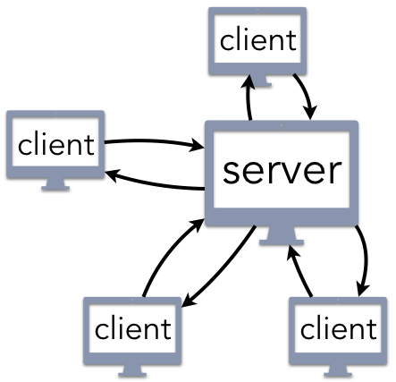
Multiple clients connect to a single server
The logical structure of the client/server architecture is a well-known and intuitive paradigm for building computer systems. The developer creates a centralized server that receives requests for service and responds accordingly. Web servers listen for requests created by a user’s web browser, the client), or an app running on a smartphone or tablet. Email servers allow you to send a message to someone else using a client application running within a web page or as part of a native email application. Network file servers can store large amounts of data, such as a collection of movies and music files; a streaming media client can then retrieve these files as indicated by the user.
When creating a client/server architecture, the first key question is to determine how the client knows how to locate the server. The uniform resource identified (URI) approach is the most common, relying on standard Internet services to fill in the details. For instance, the URI, www.example.com/index.html indicates that there is a file named index.html that can be accessed from the www.example.com web server. This answer is not entirely satisfying, because it leaves unanswered client/server architecture how you are supposed to know where to find www.example.com; the answer is you use a DNS client to contact a DNS server as a preliminary step toward using your web client to contact a web server. The main idea in this approach is that there is a single entity (the server) that provides a service to clients upon request.
Client/server architectures are common in user-focused applications, but they are also widely used in systems that do not provide visible services. As an example, several components of operating systems (OS) are designed according to a client/server architecture. For instance, the graphical user interface (GUI) is typically structured as a server that displays information in windows, manages the desktop, and directs keyboard or mouse input correctly; each application that is running acts as a client, sending requests to the GUI to update the visual display. Components that provide information about what applications are running, what the current time is, or whether a login request is allowed are all structured as servers. That is, anything that is typically described as an OS service exhibits a client/server architecture.
One advantage of the client/server architecture is the simplicity of handling updates. If a file is renamed, its contents modified, or changed in any other way, this change only needs to occur once. After the file or resource is updated on the server, the new version can be made immediately available. Relatedly, the centralized structure makes it easy to detect security breaches or data corruptions. If a user reports a broken link or some other bad result, the problem only needs to be fixed in one location.
From a communication perspective, client/server architectures rely on communication protocols, standards that specify precisely how to request a service and interpret the response. Protocols are necessary, because there are no pre-defined assumptions regarding who can be a client. Returning to the previous examples from above, a web server defaults to responding to requests from any web browser connected to the Internet. The email server that you are using will accept incoming messages from anyone, including a long-lost friend attempting to reconnect or a criminal enterprise sending you spam with a virus attached. So long as the client and server adhere to the communication protocol, messages can be delivered to and from the server. Granted, after the server receives the message, it may use a spam filter or other security mechanism to discard it without your knowledge; however, the message was still delivered to the server itself.
Client/server architectures have a key feature that is both an advantage and disadvantage: centralization. Maintaining a single server makes it easy to process changes efficiently and provide consistent service. The downside of this is that the system has a single point of failure. If the web server crashes, then the entire service is down. The single access point also creates a bottleneck when many clients try to request service at the same time. As an analogy, imagine going to a restaurant that only has one table. That is not a problem for most of the day when there are few (if any) customers arriving; however, the restaurant would quickly go out of business since it could not serve enough customers during the busy (and profitable) meal-time rushes. One way for client/server architectures to solve this problem is to use replication. Instead of using only one server, a few servers coordinate the work very closely, providing backup to each other. This would be analogous to adding more tables to the restaurant.
Peer-to-Peer (P2P) Models
This idea of replication can be extended even further to the notion of peer-to-peer (P2P architectures. The logical structure of a P2P architectures retains many of the key features of traditional client/server architectures, with the exception that every (or most) participating entities take turns acting as both clients and servers. Any node in the architecture can communicate with any other, requesting or providing service as needed.
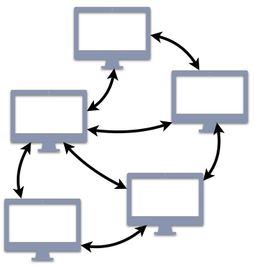
All P2P nodes are clients and servers
For many readers, P2P architectures are probably associated with file-sharing services, such as BitTorrent. In that service, you may use your client to download a file provided by another user; in return, while you are connected to the network, other users can also download that same file (or pieces of it) from your client. P2P architectures go beyond just this single application, though. Another common example of a P2P architecture is DNS, the service that translates human-readable domain names (www.example.com) into a numeric IP address. Although your web browser interacts with DNS in a traditional client/server approach, DNS itself consists of a world-wide P2P network of systems that exchange information to support these translations.
Overall, P2P architectures extend the client/server paradigm with the benefit that they scale well by maintaining good (or even better) service as the number of users increases. For instance, in a system like DNS with P2P nodes distributed world-wide, your request can be routed to the server that is physically closest to you. Consequently, your request would be handled more efficiently than if the message had to be transmitted to the other side of the world.
The tradeoff for these scaling benefits is more difficulty in both administration and security. For instance, if one of the nodes is corrupted so that it serves spam or other malware, system administrators may struggle to identify which particular node is causing the problem. Another problem that arises from this tradeoff is that updates are not guaranteed to be immediately accessible. When a file is updated on one node, that change needs to be communicated to all of the other nodes, which takes time. While this change is propagating, that file may be designated as not available or only the old version can be accessed. The choice between traditional client/server and P2P architectures must account for all of these factors.
The sections above are adapted from the OpenCSF Project (https://w3.cs.jmu.edu/kirkpams/OpenCSF/Books/csf/html/Architectures.html). Distributed under the Creative Commons Attribution-NonCommercial 4.0 International Public License (CC-BY-NC). Copyright (c) 2019-2023 – Michael S. Kirkpatrick
Network Reference Models
Two reference models have been successful in the networking community : the Internet, or TCP/IP, reference model and the OSI reference model. We discuss them briefly in this section.
Given the growing complexity of computer networks, during the 1970s network researchers proposed various reference models to facilitate the description of network protocols and services. Of these, the Open Systems Interconnection (OSI) model was probably the most influential. It served as the basis for the standardization work performed within the ISO to develop global computer network standards. The Internet (TCP/IP) model can be considered as a simplified version of the OSI reference model.
The Internet (TCP/IP) Reference Model
The Internet (TCP/IP) model is divided into five layers, as shown in the figure below.
The five layers of the Internet reference model
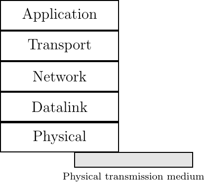
The Physical Layer
Starting from the bottom, the first layer is the Physical layer. Two communicating devices are linked through a physical medium. This physical medium is used to transfer an electrical or optical signal between two directly connected devices.
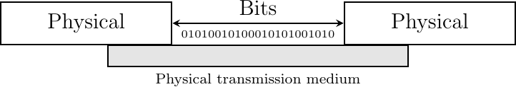
An important point to note about the Physical layer is the service that it provides. This service is usually an unreliable service that allows the users of the Physical layer to exchange bits. The unit of information transfer in the Physical layer is the bit. The Physical layer service is unreliable because :
- The Physical layer may change, e.g., due to electromagnetic interference, the value of a bit being transmitted
- The Physical layer may deliver more bits to the receiver than the bits sent by the sender
- The Physical layer may deliver fewer bits to the receiver than the bits sent by the sender
The Physical layer
The Data Link Layer
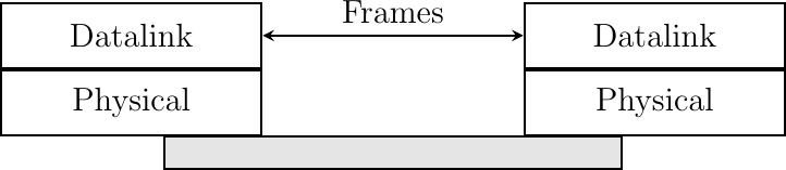
The Data Link layer builds on the service provided by the underlying physical layer. The Data Link layer allows two hosts that are directly connected through the Physical layer to exchange information. The unit of information exchanged between two entities in the Data Link layer is a frame. A frame is a finite sequence of bits. Some Data Link layers use variable-length frames while others only use fixed-length frames. Some Datalink layers provide a connection-oriented service while others provide a connectionless service. Some Data Link layers provide reliable delivery while others do not guarantee the correct delivery of the information.
An important point to note about the Data Link layer is that although the figure below indicates that two entities of the Data Link layer exchange frames directly, in reality this is slightly different. When the Data Link layer entity on the left needs to transmit a frame, it issues as many Data.request primitives to the underlying Physical layer as there are bits in the frame. The physical layer will then convert the sequence of bits in an electromagnetic or optical signal that will be sent over the physical medium. The Physical layer on the right hand side of the figure will decode the received signal, recover the bits and issue the corresponding Data.indication primitives to its Data Link layer entity. If there are no transmission errors, this entity will receive the frame sent earlier.
The Data Link layer
The Network Layer
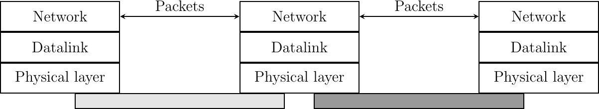
The Data Link layer allows directly connected hosts to exchange information, but it is often necessary to exchange information between hosts that are not attached to the same physical medium. This is the task of the Network layer. The Network layer is built above the Data Link layer. Network layer entities exchange packets. A packet is a finite sequence of bytes that is transported by the Data Link layer inside one or more frames. A packet usually contains information about its origin and its destination, and usually passes through several intermediate devices called routers on its way from its origin to its destination.
The network layer
The Transport Layer
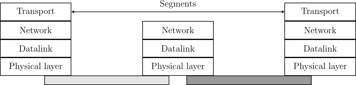
The network layer enables hosts to reach each others. However, different communication flows can take place between the same hosts. These communication flows might have different needs (some require reliable delivery, other not) and need to be distinguished. Ensuring an identification of a communication flow between two given hosts is the task of the Transport layer. Transport layer entities exchange segments. A segment is a finite sequence of bytes that are transported inside one or more packets. A transport layer entity issues segments (or sometimes part of segments) as Data.request to the underlying network layer entity.
There are different types of transport layers. The most widely used transport layers on the Internet are TCP, that provides a reliable connection-oriented bytestream transport service, and UDP, that provides an unreliable connection-less transport service.
The Transport Layer
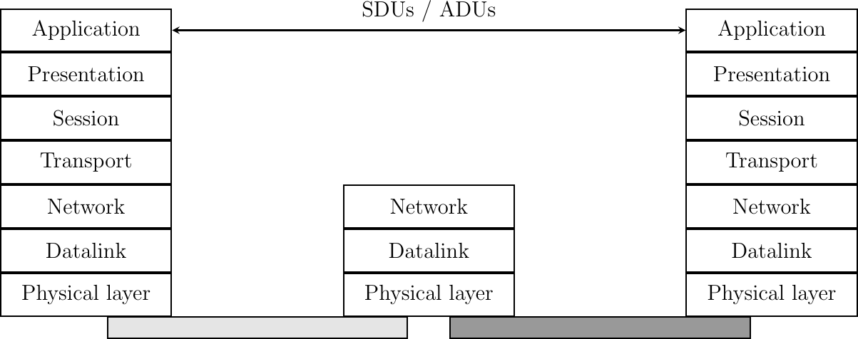
The Application Layer
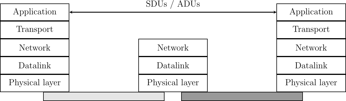
The upper layer of our architecture is the Application layer. This layer includes all the mechanisms and data structures that are necessary for the applications. We will use application data unit (ADU) or the generic service data unit (SDU) term to indicate the data exchanged between two entities of the Application layer.
The Application Layer
In the remaining chapters of this text, we will often refer to the information exchanged between entities located in different layers. To avoid any confusion, we will stick to the terminology defined earlier, i.e. :
- physical layer entities exchange bits
- datalink layer entities exchange frames
- network layer entities exchange packets
- transport layer entities exchange segments
- application layer entities exchange SDUs
- The Application layer
- The Transport layer
- The Internet layer, which is equivalent to the network layer of our reference model
- The Link layer which combines the functions of the physical and datalink layers of our five-layer reference model
Besides this difference in the lower layers, the TCP/IP reference model is very close to the five layers that we reference here.
The OSI Reference Model
Compared to the five layers reference model explained above, the OSI reference model defined in is divided in seven layers. The four lower layers are similar to the four lower layers described above. The OSI reference model refined the application layer by dividing it in three layers :
- The Session layer contains the protocols and mechanisms that are necessary to organize and to synchronize the dialogue and to manage the data exchange of presentation layer entities. While one of the main functions of the transport layer is to cope with the unreliability of the network layer, the session’s layer objective is to hide the possible failures of transport-level connections to the upper layer higher. For this, the Session Layer provides services that allow establishing a session-connection, to support in-order data exchange (including mechanisms that allow recovering from the abrupt release of an underlying transport connection), and to release the connection in an orderly manner.
- The Presentation layer was designed to cope with the different ways of representing information on computers. There are many differences in the way computer store information. Some computers store integers as 32 bits field, others use 64 bits field and the same problem arises with floating point number. For textual information, this is even more complex with the many different character codes that have been used. The situation is even more complex when considering the exchange of structured information such as database records. To solve this problem, the Presentation layer provides a common representation of the data transferred. The ASN.1 notation was designed for the Presentation layer and is still used today by some protocols.
- The Application layer that contains the mechanisms that do not fit in neither the Presentation nor the Session layer. The OSI Application layer was itself further divided in several generic service elements.
The seven layers of the OSI reference model
This sections above are adapted from “Computer Networking : Principles, Protocols and Practice, 3rd Edition” by Olivier Bonaventure (2019), Université catholique de Louvain (UCL), licensed under CC BY-NC-SA 4.0 as a derivative from this page of the original work
OSI Mnemonics
Several mnemonics exist for remembering the OSI model from a top-down or bottom-up approach. Do you have a favorite or one of your own?
From Application to Physical (Layer 7 to Layer 1)
- All People Seem To Need Data Processing
- All Pros Search Top Notch Donut Places
- All Prudent Students Take Notes During Periods
From Physical to Application (Layer 1 to Layer 7)
- Please Do Not Throw Sausage Pizza Away
- Please Do Not Tell Salespeople Anything
- Please Do Not Teach Smart People Acronyms
For an overview of the OSI model from a security standpoint, watch this video: OSI Model Layer Attacks, Mitigation & Protocols | Cybersecurity Analyst Training 101 (Cyber Gray Matter, 2022).
An architecture for computing that enables the separation of functions between front-end data entry and display (client) and back-end request processing (server) in order to bolster the productivity and efficiency of each. This form of distributed computing aims to spread the workload between two devices connected via a network. A smartphone or computer web browser communicating with a Google web server to return results for a query requesting "what is client-server computing" is an example of the client-server architecture in action.
Sulyman, Shakirat. (2014). Client-Server Model. IOSR Journal of Computer Engineering. 16. 57-71. 10.9790/0661-16195771.
