Want to create or adapt books like this? Learn more about how Pressbooks supports open publishing practices.
6. The Network Layer I | Addressing
Chapter Objectives
6-1 Differentiate between the data and control planes of the Network Layer.
6-2 Summarize the components of an IP packet header.
6-3 Explain the IPv4 classes and their use in different types of networks.
6-4 Demonstrate the purpose and function of subnets and network address translation (NAT).
6-5 Summarize the purpose and features of IPv6.
The Data Plane and the Control Plane
As noted in the overview, the OSI model layer built above the data link layer is the network layer. Similar to frames on the data link layer, its method of data exchange is in the form of a datagram. The datagram contains source and destination information as it passes through several intermediate devices called routers on its way from its source to its destination. We will discuss this information in this section, and how it is routed in the next.
The network layer operates on two planes, the data plane and the control plane. Consider taking a trip by plane. The data plane acts as the plane that transports passengers to the correct destination (or forwards the passengers). The control plane works as the traffic controller that controls and routes traffic.
The data plane performs tasks like receiving and inspecting the packets, forwarding them to the correct destination, queuing network packets during network congestion, and ensuring the safe delivery of packets to the correct destination. It accomplishes these tasks by leveraging the Internet Protocol and Ethernet. The data plane operates at a lower abstraction level than the control plane — forwarding packets based on the routing configured by the control plane.
The control plane is responsible for determining the “best” routing and path configuration, with protocols such as OSPF, RIP, and BGP. These enable the control plane to exchange routing details for optimal network traffic paths. The control plane typically operates separate from the data plane, allowing for greater efficiency and scalability. It is also distributed and centralized. We’ll return to the control plane in the next chapter.
The IP Datagram
As you recall, a packet is also called a datagram, a segment, a block, a cell, or a frame depending on the protocol used for the transmission of data. In this section, we’ll use the term datagram. The IP header is a crucial component of the IP protocol that is used to transport data across the Internet. This header is a part of the datagram that is transmitted over the Internet and contains important information about the source and destination of the data.
When data has to be transmitted, it is broken down into similar structures of data before transmission. Once they reach their destination the pieces are reassembled into the original data chunk.
The structure of a datagram depends on the type of packet it is and on the protocol. Normally, packets have a header and a payload.
The header keeps overhead information about the packet, the service, and other transmission-related data. For example, data transfer over the Internet requires breaking down the data into IP packets, as defined in the IP (Internet Protocol). An IP packet includes:
The source IP address, which is the IP address of the machine sending the data.
The destination IP address, which is the machine or device to which the data is sent.
The sequence number of the packets, a number that puts the packets in order such that they are reassembled in a way to get the original data back exactly as it was prior to transmission.
The type of service
Any relevant flags
Some other technical data
And finally, the payload, which represents the bulk of the packet (all the above is considered as overhead), and contains the actual data being transmitted. This can be any type of data, such as text, images, or video. The payload is usually encrypted for security purposes, especially when sensitive data is being transmitted.
Figure 4-1: An IP Datagram (Attribution: Michel Bakni, CC BY-SA 4.0 https://creativecommons.org/licenses/by-sa/4.0, via Wikimedia Commons)
The IP datagram is an essential component of the TCP/IP suite, which is used for communication on the Internet. Without IP datagrams, computers would not be able to communicate with each other over the Internet. IP datagrams are used in conjunction with other protocols, such as TCP and UDP, to ensure that data is transmitted reliably and efficiently.
To see how a packet travels the Internet, watch this video from the World Science Festival [3:29]:
IPv4 Addressing
The network layer enables the transmission of information between hosts that are not directly connected through intermediate routers. To send one byte of information to host B, host A needs to place this information inside the datagram. An IP address is a numeric identifier assigned to each machine on an IP network. It designates the specific location of a device on the network.
An important issue in the network layer is the ability to identify a node (host or router) inside the network. This identification is performed by associating an address to each node. An address is usually represented as a sequence of bits. Most networks use fixed-length addresses. At this stage, let us simply assume that each node in a network has an address that corresponds to the binary representation of its name.
Concepts Corner
Let’s review some important terminology associated with an IPv4(Internet Protocol Version 4) address.
Bit – A bit is one digit, either a 1 or a 0.
Byte – A byte is 8 bits.
Octet – An octet, made up of 8 bits, is just an ordinary 8-bit binary number.
Network address – This is the designation used in routing to send packets to a remote network – for example, 10.0.0.0, 172.16.0.0, and 192.168.1.0.
Broadcast address – The address used by applications and hosts to send information to all nodes on a network is called the broadcast address. Examples include 255.255.255.255, which is all networks, all nodes; 172.16.255.255, which is all subnets and hosts on network 172.16.0.0; and 10.255.255.255, which broadcasts to all subnets and hosts on network 10.0.0.0.
An IP address consists of 32 bits of information. These bits are divided into four sections, referred to as octets or bytes, each containing one byte (8 bits). You can depict an IP address using one of these methods:
Dotted-decimal, as in 172.20.18.125
Binary, as in 10101100.00010100.00010010.01111101
The 32-bit IP address is a structured or hierarchical address, as opposed to a flat or nonhierarchical address. Although either type of addressing scheme could have been used, hierarchical addressing was chosen for a good reason. The advantage of this scheme is that it can handle a large number of addresses, namely 4.3 billion (a 32-bit address space with two possible values for each position – either 0 or 1 – gives you 232, or 4,294,967,296. Each octet can have a value from 0 to 255 in decimal notation, or from 00000000 to 11111111 in binary notation. For example, the address 192.168.0.1 has the following binary representation: 11000000.10101000.00000000.00000001.
The network address (which can also be called the network number) uniquely identifies each network. Every machine on the same network shares that network address as part of its IP address. In the IP address 172.20.18.125, for example, 172.20 is the network address. The node address, also referred to as a host address, is assigned to, and uniquely identifies, each machine on a network. This part of the address must be unique because it identifies a particular machine, that is, an individual node, as opposed to a network, which is a group. In the sample IP address 172.20.18.125, the 18.125 is the node address. The designers of the Internet decided to create classes of networks based on network size. For the small number of networks possessing a very large number of nodes, they created the rank Class A network. At the other extreme is the Class C network , which is reserved for the numerous networks with a small number of nodes. The class distinction for networks between very large and very small is predictably called the Class B network .
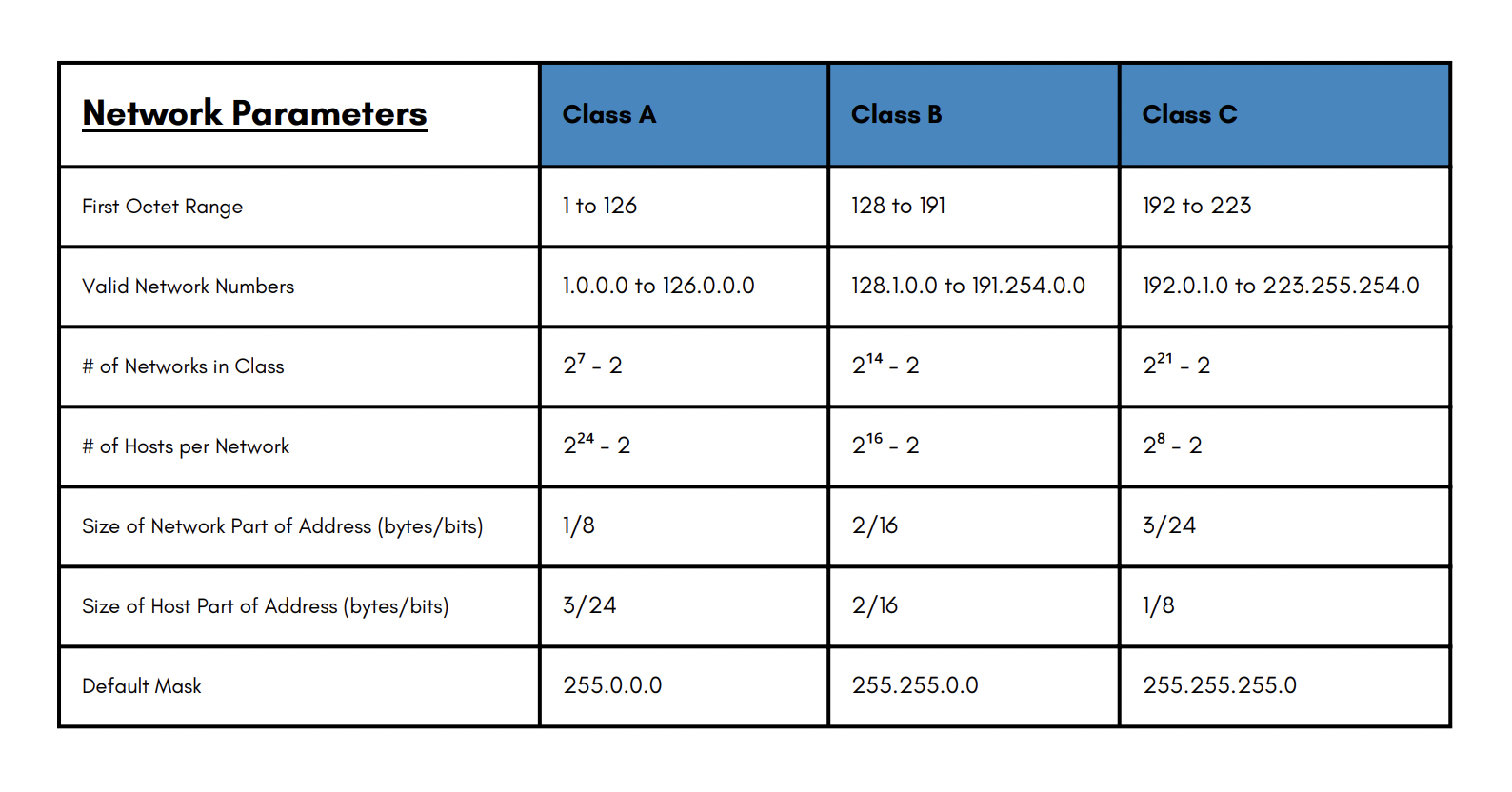
More specifically, IPv4 addresses are classified into five classes: A, B, C, D, and E. Each class has a different range of values for the first octet, and a different default subnet mask. The classes are:
Class A: The first octet ranges from 1 to 126, and the default subnet mask is 255.0.0.0. This means that there can be up to 126 networks, each with up to 16 million hosts. For example, the address 10.0.0.1, reserved for the class A space, specifies “10.” as the network portion and “.0.0.1” as the host portion.
Class B: The first octet ranges from 128 to 191, and the default subnet mask is 255.255.0.0. This means that there can be up to 16 thousand networks, each with up to 65 thousand hosts. For example, the address 172.16.0.1 belongs to class B, and specified the network part as “172.16.” and the host part as “.0.1”.
Class C: The first octet ranges from 192 to 223, and the default subnet mask is 255.255.255.0. This means that there can be up to 2 million networks, each with up to 254 hosts. For example, the address 192.168.0.1 belongs to class C, and specified the network part as “192.168.0.” and the host part as “.1”.
Class D: The first octet ranges from 224 to 239, and these addresses are reserved for multicast purposes, which means they are used to send data to multiple hosts at once.
Class E: The first octet ranges from 240 to 255, and these addresses are reserved for experimental purposes.
Figure 4-2: IPv4 addresses
By definition, an IP address that begins with 8 in the first octet is in a Class A network, so the network part of the address is the first byte, or first octet. An address that begins with 130 is in a Class B network. By definition, Class B addresses have a 2-byte network part, as shown. Finally, any address that begins with 199 is in a Class C network, which has a 3-byte network part. Also by definition, a Class A address has a 3-byte host part, Class B has a 2- byte host part, and Class C has a 1-byte host part.
Some special types of IPv4 addresses have different functions or meanings:
Loopback address: This is the address 127.x.x.x (usually written as 127 .0 .0 .1 ), which is used to test the connectivity of a device with itself.
Broadcast address: This is the address that has all bits set to 1 in the host part (usually written as x.x.x ** .255** ), which is used to send data to all hosts on a network.
Network address: This is the address that has all bits set to 0 in the host part (usually written as x.x.x ** .0** ), which is used to identify a network as a whole.
Private addresses: These are addresses that are not routable on the internet, which means they can only be used within a private network or behind a router that performs NAT (Network Address Translation). NAT is discussed at the end of this chapter. There are three ranges of private addresses:
10 .x.x.x (class A)
172 .16.x.x – 172 .31.x.x (class B)
192.168.x.x (class C)
Network Segmentation
IPv4 addresses are used to identify both networks and hosts on the internet. A network is a group of devices that can communicate with each other, and a host is a device that has an IP address assigned to it. To distinguish between the network and host parts of an address, a subnetmask is used. A subnet mask is another 32-bit number that has 1s in the network part and 0s in the host part. For example, the subnet mask 255.255.255.0 has the following binary representation: 11111111.11111111.11111111.00000000.
Network segmentation can improve network performance by subdividing network traffic, and also facilitates network security by isolating network domains by address space. The process of dividing an address range into smaller address spaces is known is called subnetting.
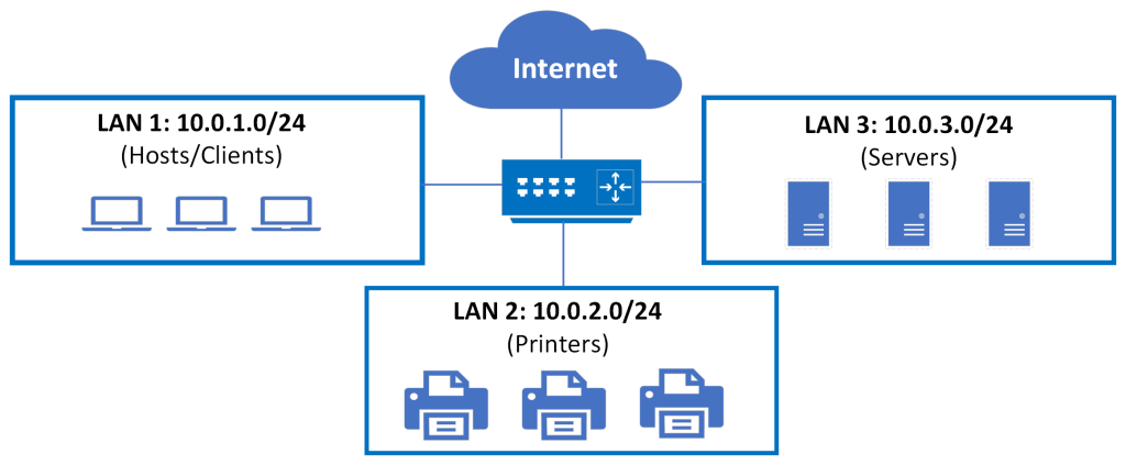
Network administrators may group address spaces into subnets by various features, including by locations in a building, types of devices (as shown below), organizational units, etc. We’ll explain how to configure subnetting next.
Figure 4-3: A sample network segmentation
IP subnetting creates vastly larger numbers of smaller groups of IP addresses compared with simply using Class A, B, and C conventions. The Class A, B, and C rules still exist, but with subnetting, a single Class A, B, or C network can be subdivided into many smaller groups. Subnetting treats a subdivision of a single Class A, B, or C network as if it were a network itself. By doing so, a single Class A, B, or C network can be subdivided into many nonoverlapping subnets.
With subnetting, the third part of an IP address, namely, the subnet appears in the middle of the address. This field is created by “borrowing” bits from the host part of the address. The size of the network part of the address never shrinks. In other words, Class A, B, and C rules still apply when you define the size of the network part of an address. The subnet mask tells us how many bits are used for the network part and how many bits are used for the host part of an address. The more bits are used for the network part, the fewer bits are available for the host part, and vice versa. This affects how many networks and hosts can be created with a given address range.
However, the host part of the address shrinks to make room for the subnet part of the address, as shown below.
Figure 4-4: Creating subnetworks.
Constructing an IP Network Addressing Scheme
We can now consider best practices in allocating IP addresses. We are going to describe classful and classless operations, including use of subnets. Using real-life examples we will describe the process of calculating subnet host addresses. In doing so, we will describe the use of subnet masks, and how they are used by routers.
Flat Topology
When talking about routing one tends to think about forwarding packets to remote destinations. The immediate thought is WAN and the Internet; however, routing also makes sense in a campus network or smaller local area networks for the purposes of traffic segmentation. If we do not have routing, then we are talking about one flat network or flat topology where all devices belong to the same logical segment. A logical segment is a broadcast domain where, in a flat topology, all devices share the same broadcast domain and receive each others’ broadcasts. This design impacts performance and throughput in the network. The only intelligence in filter mechanism would be a Layer 2 switch, which forwards based on MAC addresses. MAC addresses have no hierarchical structure and therefore, we are still talking about a flat network. The more machines and devices you add, the more performance degradation you are going to experience. Routers can be used in these scenarios to break the network into multiple broadcast domains or subnets.
Subnetworks
Advantages to subnets are not only on the performance side. With the segmentation in multiple subnets, overall traffic is reduced and each subnet is a broadcast domain.
A router is effective at stopping local broadcasts, but there are more advantages available with subnetting. You are breaking things into smaller pieces and this divide-and-conquer approach will make things easier to manage. By compartmentalizing the network you can apply different policies to each individual compartment. The router would be the overall policy in force because it controls traffic from one subnet to the other, effectively isolating network problems. If something happens on one subnet the effect is mitigated by the router in other subnets.
Security is also enhanced with subnetting. A denial of service (DoS) attack may not reach other subnets if the router is acting as some sort of a firewall in the middle, regardless of the reason for subnetting. We would need to assign each subnet a different network or subnet ID and then hosts within that subnet would have a unique host ID portion of the IP address.
What Does Subnet Mask Do?
How can we tell which portion of the IP address is the network and which portion is the host? In classful routing, the class would tell us which bytes are dedicated to the network ID and which bytes are dedicated to the host. When we subnet a classful IP address, what we are doing is stealing bits from the host portion of the address and then making them part of the subnet portion of the address. We are effectively creating a third leg of the hierarchy. We are going to have the network defined by the class, but also a subnet and also then the host. We are dividing networks into subnets and then subnets contain hosts.
This is a hierarchy that is similar to our telephone numbering system; we have country codes and then city codes and then telephone numbers. Telephone numbers require the city code outside a city, and a country code outside a country to provide a unique number. When we do this, we are talking about a classless environment. In classless routing, the class of the address no longer tells us what portion of the address is network, subnet, or host. It is in the subnet mask, the one component that will tell us each section. In this context, then the mask is not similar to the Halloween masks that your kids may use. This is a mask that serves as a pair of glasses to look at the addresses differently. It is a measuring tool that tells you how far to look into the IP address to find the network piece, then the subnet piece, and then what is left is the host piece.
Possible Subnets and Hosts for a Class C Network
Classless Inter-Domain Routing is also called CIDR, and that’s what we will discuss next. The subnet mask is used by hosts to identify traffic that travels outside of their own subnet. It is also used by routers to identify networks and subnets to forward traffic toward those destinations. In more specific terms, it is nothing more than a tool for borrowing bits, the example here is a class C network. The classful paradigm tells us that the first three bytes of the address represent the network portion, whereas the last byte represents the host portion. Well, when subnetting, we want to create subnets out of the network; the network bytes are fixed and so we are going to need to use some of the bits dedicated to the host as subnet bits. One reminder here is that we are borrowing bits; in other words, the more bits we take from the host portion, the fewer hosts we are going to be able to represent, but the more subnets we will have. Consequently, the number of subnets and the number of hosts depends on the number of bits we borrow. When these bits are borrowed, the quantity of subnets possible will be 2 to the power of the number of bits borrowed.
Network.Network.Network.Host
Figure 4-5: Class C addresses
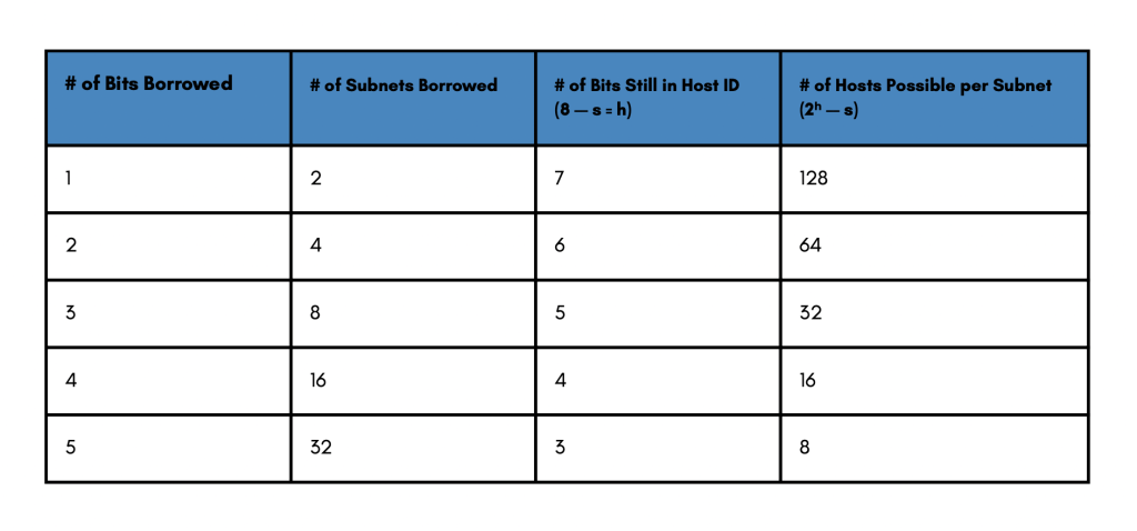
In a class C address we will call the number of borrowed bits S and the number of hosts H, where H is nothing more than 8-S (8 bits minus the number of bits borrowed). Again, the more subnet bits we borrow, the fewer hosts we are going to have and the total bits we have available to borrow in a class C is 8. With 1 bit, we are going to be able to represent 2 to the first power as a number of subnets, or two subnets. That leaves us with the 7 bits for the host, which equates to 126 possible hosts per subnet. Notice that 2 to the seventh power is 128, but we do have 2 reserved addresses, all 0s and all ls. Neither can be used as a host address because those are reserved; they represent the network itself and the broadcast. You can reach similar conclusions if you increase the number of bits borrowed. The more bits you borrow, the more subnets you will have, the fewer hosts you will have.
Possible Subnets and Hosts for a Class B Network
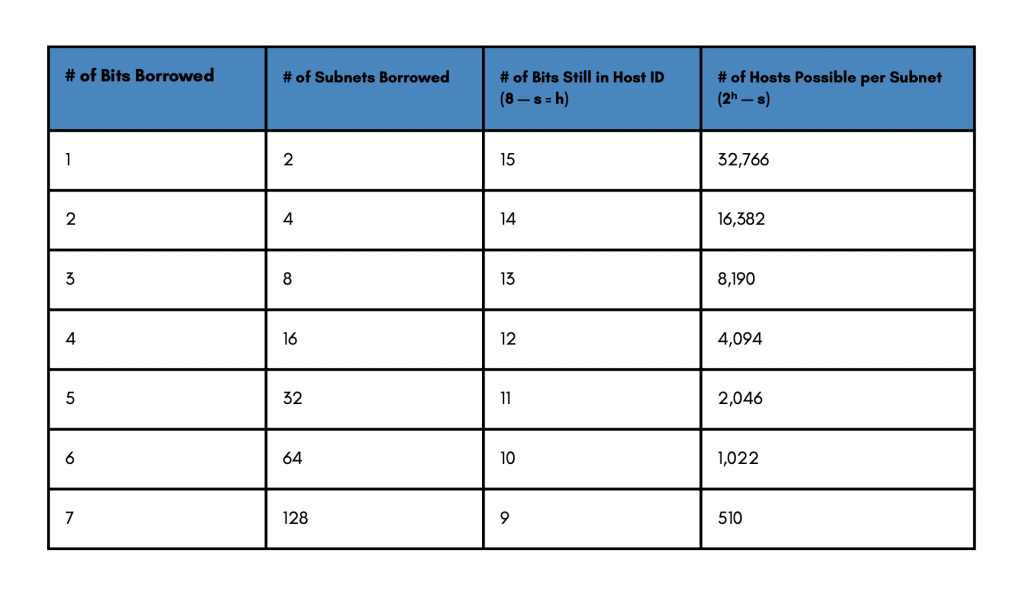
In this class B example, we have more room to borrow bits from the host portion. But it follows the similar process and a similar logic. In this example, we borrow, let us say, 4 bits. That means we have room for 16 subnets out of the class B network, leaving us with 12 bits for the host. This time we have 16 subnets available minus 4 bits borrowed leaves 12 bits for the host. Raising 2 to the 12th power gives us 4096 possible hosts. Again, we have to subtract the two reserved addresses giving us 4094 hosts for each one of the four subnets.
Network.Network.Host.Host
Figure 4-6: Class B addresses
Possible Subnets and Hosts for a Class A Network
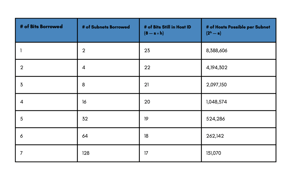
The same goes for class A addresses. This class is probably the most flexible one in terms of subnetting because we have a lot more bits to borrow, explaining why one of the most popular IP addresses or network addresses is the class A 10.x.x.x private address block. With that, you can actually borrow the whole second byte to represent your subnets and still you have a few thousand hosts available per subnet.
Network.Host.Host.Host
Figure 4-7: Class A addresses
End System Mask Operation
End systems and hosts will use the subnet mask to identify the network that they are located at in terms of the IP hierarchy. They will then compare that network with the destination address of their packets. If the destination matches their own network according to the mask, they will try to send an ARP request to obtain the MAC address of the destination. It will then forward a packet straight to the destination in the local subnet.
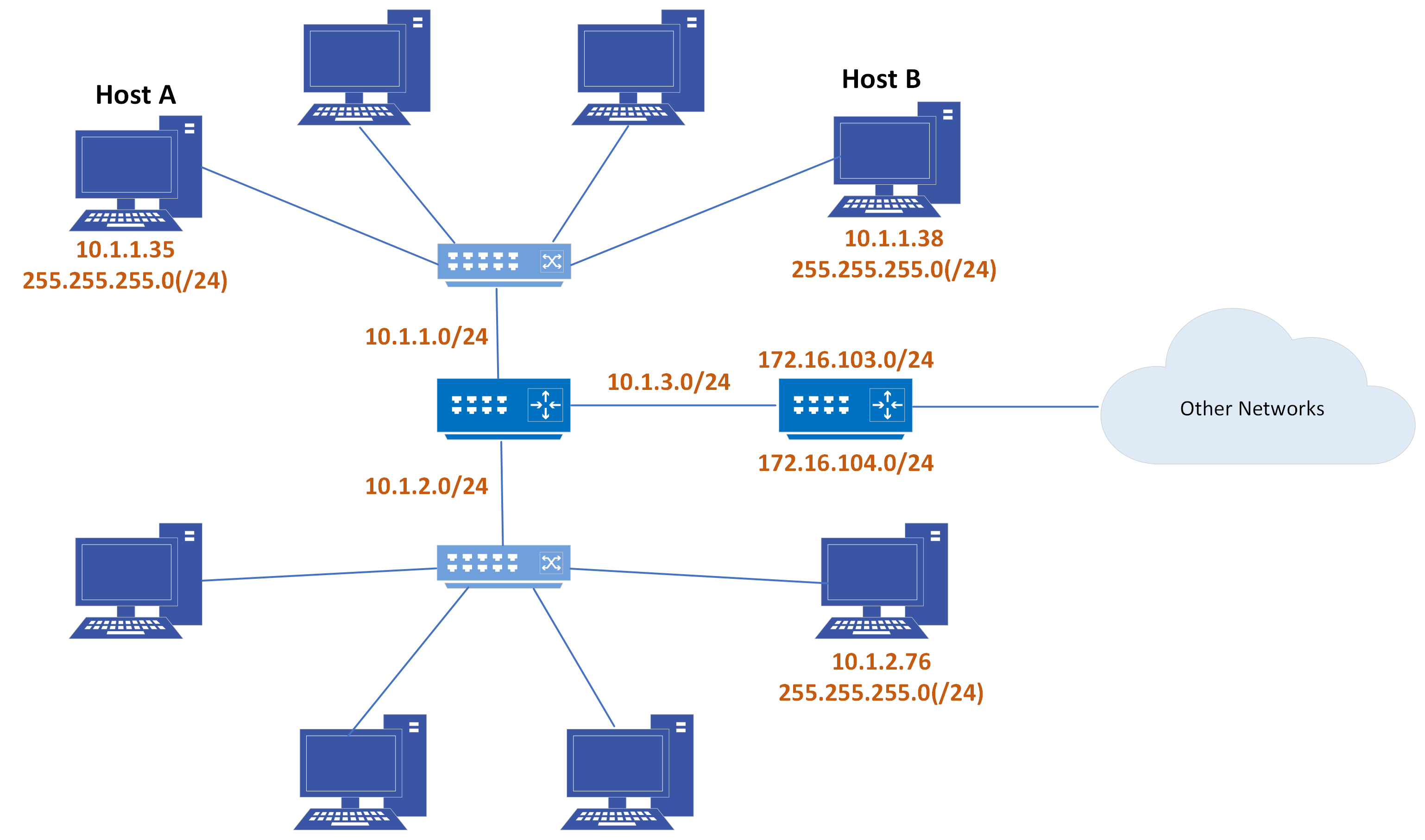
Figure 4-8: A sample network
If the networks do not match on the other hand, then that means the destination is another remote network and they will need to resolve for the router’s IP address. The router is the component that will take them to or forward their packets to the remote destination. The router’s IP address is nothing more than the default gateway configured in each one of the machines.
How Routers Use Subnet Masks
The function of the subnet mask is the same in the case of routers, but the routers are going to use the information differently. They will receive packets in understanding that they are responsible for forwarding them to the intended destination. They will use the mask to compare the destination IP with the known destinations in the routing table. In this example, the naming convention for the subnet mask is “/” followed by the number, where the number tells the router which bits are the network portion of the address.
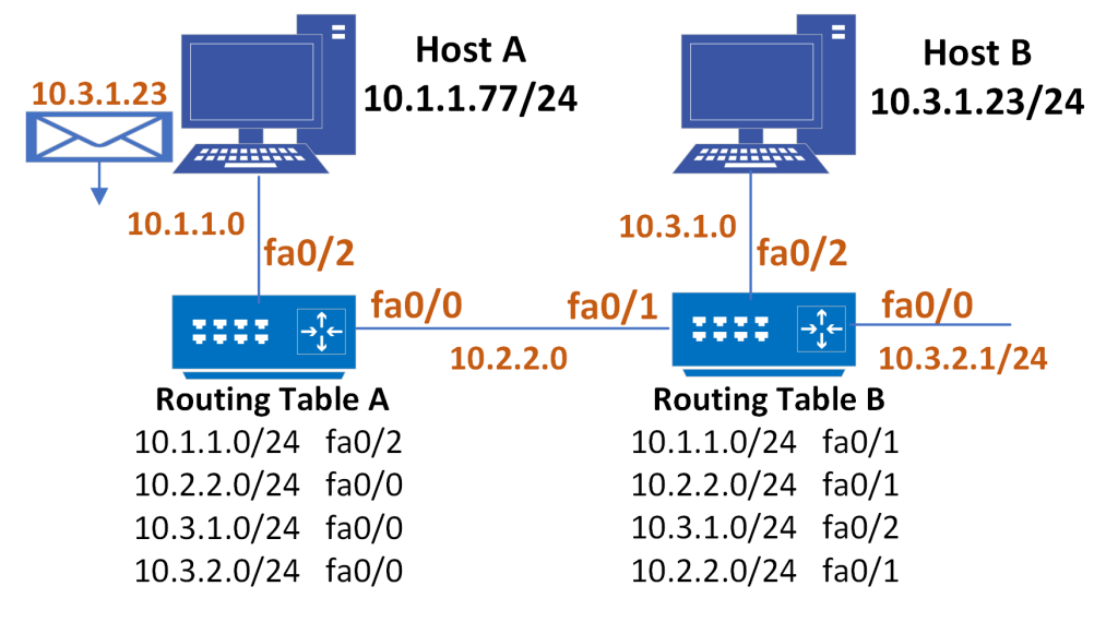
A /24 means that the first 3 bytes or 24 bits are the network portion of the address. Also, in the example below, host A is trying to send packets to destination 10.3.1.23; that host will use the mask /24 to compare its own subnet ID. Using the subnet mask, the host will compare is subnet ID (10.1.1) with the first 3 bytes of the destination subnet ID (10.3.1). They do not match, so host A will send the packet to the router. The router then will use the /24 mask to compare the first three bytes of the received packet’s destination IP to match the destination subnet to the entries in the routing table. It will find that there is an entry that matches the destination. Not only that, but it follows that the outgoing interface to forward that packet through is fa0/0. That is how the packet reaches router B, which follows the same procedure and delivers the packet to the directly connected subnet.
Figure 4-9: Sample router configuration
Applying the Subnet Address Scheme
When subnetting the network, we need to make sure of several things. First, we need to plan our subnetting scheme and our subnetting strategy to borrow as many bits from the host portion of the address as needed to represent the number of subnets and hosts. When that design portion is complete, then we need to allocate and assign the subnets to actual network segments. The subnet mask is a tool that will tell all devices, hosts, and routers how to read the destinations and how to forward packets accordingly.
Octet Values of a Subnet Mask
We know why we need subnet masks, but what does one look like and how do we build them and design them? Well, a subnet mask will be nothing more than a 4-byte word similar to an IP address. In other words, it is a string of 32 bits, 1s or 0s. Essentially, the subnet mask looks like an IP address, but is not. Instead, it is sent along with the IP address to allow you to identify the host portion of the address, the subnet ID, and network portions of the address. In that sense, all 1s in the subnet mask indicate that the corresponding bits of the IP address are part of the network portion of the address. All 0s in the subnet mask indicate that the corresponding bit of the IP address will be part of the host portion of the address.
Now remember, we said that subnet masks are nothing more than a borrowing mechanism. We will shift the default mask to the right, borrowing bits from the host portion of the address. Doing so results in one of the key features of the subnet mask which is that the 1s are always consecutive and so are the 0s.
Figure 4-10: Subnet masks
As we move down this diagram, this makes sense in terms of our knowledge of the binary to decimal conversions. In the end, all 1s in a subnet mask constitute the binary representation of the decimal number 255. This number is the greatest subnet mask, or the representation of the subnet mask in decimal numbers, for any byte. That is why 24 consecutive bits set to 1 results in the subnet mask 255.255.255.0.
Default Subnet Masks
In the case of a class A address, the 10.0.0.0 is the default subnet mask, and the one that tells us how the address class identifies the network portion of the address. Specifically, the first octet is all 1s and the rest of the three bytes are 0s. This corresponds to 255.0.0.0 in decimal notation. What is the /8 then? Instead of typing 255.0.0.0, designating /8 will give us a mask with 8 consecutive bits set to one and the rest are 0s. This highlights another feature of subnet masks.
Figure 4-11: Default subnet masks
When we subnet, we always start from the left and move to the right in defining the number of bits set to 1 that will give us the network and subnet IDs. Knowing that a subnet mask has 32 bits, all we need to know is how many bits are set to 1, because with that we know that the rest of the bits will be a consecutive string of 0s. Something similar happens in classes B and C. For class B, 172.16.0.0, is the default mask, the one that tells us that the class one is 2 bytes set to 1 that is 255.255.0.0 or /16. The same thing is true for class C addresses with that default mask, which is nothing more than a /24.
Procedure for Implementing Subnets
It is now time to look at this as a process in which we obtain an IP address from a registry authority like IANA(Internet Assigned Numbers Authority) and then split it into multiple subnets. We get one network, but we will need more than one, because most likely we do not have a flat structure or topology. The number of segments in our network will give us the number of subnets we need. It is time then to define a new subnet mask that extends the default mask to the right. Well, we know that the subnet mask is nothing more than a borrowing tool and so we will go ahead and calculate the number of bits we need to borrow in order to represent the number of subnets required.
Remember that every bit we borrow from the host will take away from the host number. The more subnets we have, the fewer hosts per subnet. With that in mind, we will reach a new subnet mask. It will most likely be a string of 1s and 0s, rather consecutive 1s followed by consecutive 0s. It will be our job to make it a decimal value and represent it in dotted decimal notation. With the new mask, it is now time to define the subnets. In other words, it is similar to creating or generating area codes. If we compare the network that was given by the registry authority to a country code, the subnets we create will be equivalent to the area codes. The hosts that fall within each subnet would then be the specific phone numbers. Here is an example: +1 (214) 123-4567 or +Network (Subnet) Host-Address. Each network segment will be allocated a different unique subnet ID within the network and then each host will need to have unique host identifiers within the subnet to create our hierarchy. When the planning is done, it is time to go into each host, device, and router and apply the IP addressing scheme with the appropriate mask.
This section is adapted (Bingman, Mitra) from “IP Network Addressing Scheme | Class A B C Subnets.” Learncisco.Net, https://www.learncisco.net/courses/icnd-1/lan-connections/network-addressing-scheme.html. Accessed 16 Sept. 2023. Except where otherwise noted, content on this site is licensed under a Creative Commons Attribution 4.0 International license.
Wrap up your understanding of IPv4 addressing and subnetting with this CertBros video [17:54]. Then move onto to NAT!
Network Address Translation (NAT)
Whether your network is the home or the corporate type, if it uses the private IP addresses, you have to translate your private inside addresses to a global outside address by using NAT. The main idea is to conserve Internet global address space, but it also increases network security by hiding internal IP addresses from external networks. In NAT terminology, the inside network is the set of networks that are subject to translation. The outside network refers to all other addresses – usually those located on the Internet. However, it’s important to understand that you can translate packets coming into the private network as well. NAT operates on a router – generally only connecting two networks together – and translates your private (local) addresses within the internal network, into public (global) addresses before any packets are forwarded to another network. This functionality gives you the option to configure NAT so that it will advertise only a single address for your entire network to the outside world. Doing this effectively hides the internal network from the whole world really well, giving you some much-needed additional security.
There are different flavors of NAT:
Static NAT – Designed to allow one-to-one mapping between local and global addresses. This flavor requires you to have one real Internet IP address for every host on your network.
Dynamic NAT – Designed to map an unregistered IP address to a registered IP address from out of a pool of registered IP addresses. You don’t have to statically configure your router to map an inside to an outside address as in static NAT, but you do have to have enough real IP addresses for everyone who wants to send packets to and from the Internet.
Overloading – This is the most popular type of NAT configuration. Overloading is a form of dynamic NAT that maps multiple unregistered IP addresses to a single registered IP address (many-to-one) by using different ports. Therefore, it’s also known as Port Address Translation (PAT). By using PAT (NAT Overload), you can have thousands of users connect to the Internet using only one real global IP address. NAT Overload is the reason we have not run out of valid IP address on the Internet.
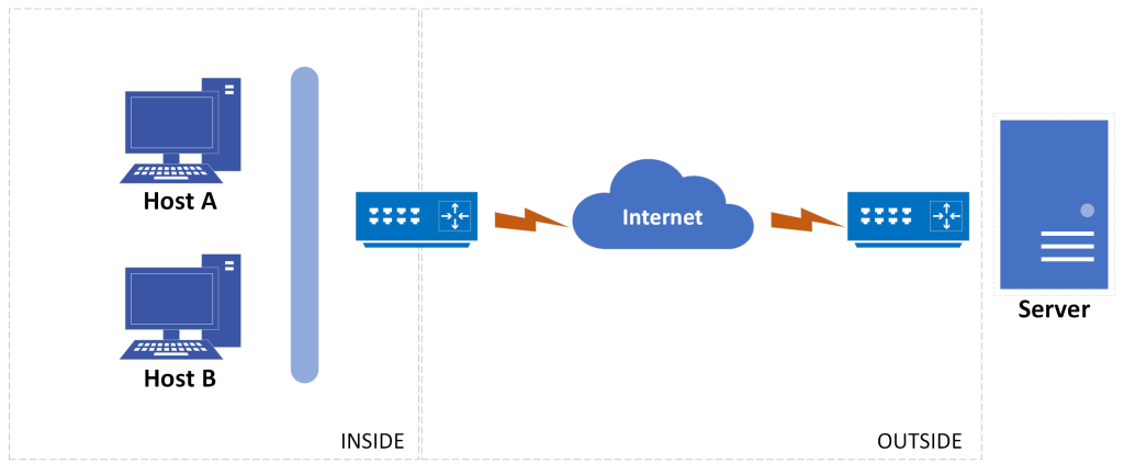
A logic diagram for NAT point of view is shown below.
Figure 4-12: Sample NAT diagram
Most typical NAT features change only the IP address of “inside” hosts. The outside host IP address can also be changed with NAT. When that occurs, the terms outside local and outside global are used to denote the IP address used to represent that host in the inside network and the outside network, respectively.
This video explains how NAT is used in public and private networks before we discuss IPv6 addresses.
IPv6 Addressing
Finally, as you’ve learned by now, we are running out of IP version 4 addresses. Classless interdomain routing, or CIDR, and Network Address Translation, or NAT, and subnetting subnets have attempted to “address” this issue. IP version 6 is a new addressing scheme to provide an almost unlimited number of addresses.
Issues with IPv4 Addressing
One of things that helped us so much in IP version 4 is almost completely gone in IPv6, Network Address Translation. You may not have been around for the beginnings of proxy servers and NAT, but admins with all of the different applications had to get used to working through NAT, and the technology has caught up with it. IPv6 moves away from this idea of private and public networks. Instead, we look for global IP addresses, which are equivalent to public IP addresses. The only local, or private, addresses in this case would be self-assigned addresses. Therefore, with a much more global network where everybody who connects up to it, NAT is expanded to have end-to-end reachability without some intermediary reworking IP addresses on the fly.
What is IPv6? Features
All right, so first and foremost with IPv6 – we have many, many more addresses. How many? 3.4 x 1038 addresses. But let’s put it in perspective, an IPv4 was how many bits? Just 32 bits. IP version 6 addresses are 128 bits. This is a significant increase in size.
A quadrupling of the bit size grows by 2 to the 96th power, well beyond what IPv4 brings to the table. That larger address base affords us a reason to move to this, namely, scalability. However, a move over to this technology gives us more than a larger address base, although this might be the driving factor. There are some other benefits. IPv6 is very flexible. It allows for route summation. It allows us to connect up to networks and have IP addresses in multiple networks. It also allows more plug-and-play features, self-assigned addresses, and renumbering for switching service providers, all on the fly. A simpler header to make it easier for routers and the core of networks to be able to forward millions, billions, trillions of packets. Security is an important feature, with Internet Protocol Security (IPsec), which is built-in. If you run IPv6, you must be capable of working with IPsec.
However, IPv4 is not going away anytime soon. Therefore, we’re going to have a hodgepodge, the old living with the new. That means we’re going to lean on strategies that allow us to run both.
IPv6 addresses
At this point, are you able to pick an IP version address out of a lineup? If we provided you a list, would you know what is valid, what is not valid? That is an important skill to have when it comes to the real world as well. Let’s talk about our IPv6 format. We already said it is 128 bits long, but we do not break it up in dotted decimal notation, as in IPv4.
Here are some examples of how an IPv6 looks:
2031:0000:130F:0000:0000:09C0:876A:130B
FF01:0000:0000:0000:0000:0000:0000:0001
0000:0000:0000:0000:0000:0000:0000:0001
0000:0000:0000:0000:0000:0000:0000:0000
You see, our IP version 6 addresses utilize hexadecimals, so we have values from 0 through 9 and then A, B, C, D, E, and F that we can find. Specifically, we group together four hexadecimal values and then append a colon, and we will do this eight times. So we have eight fields that contain four hexadecimal digits. Let’s think about that. How big are each of these fields? Well each hexadecimal value equates to 4 bits, so four times four would be 16 bits. So we have eight 16-bit fields for a total of 128 bits. Look at the examples provided. These are really long addresses. We had enough problems remembering 192.168.1.8. Try remembering these. It is much, much more difficult. But is this how they are always represented? No, they are not. There are mechanisms in place to shrink them down, truncate them, to make them more manageable, to make them easier to read and it is not just for us, our devices do this as well. So let’s talk about some of these mechanisms here. The first one being to drop leading zeros.
Here are some examples:
2031:0:130F:0:0:09C0:876A:130B
FF01:0:0:0:0:0:0:1
0:0:0:0:0:0:0:1
0:0:0:0:0:0:0:0
Look inside one of those fields. Anytime a field starts with a 0, you can take that 0 off. If the next value within that field is a 0, you can take that one off as well. You can remove the first three hexadecimal values in a field if they are zeros. We cannot remove all four because we still have to have a value in there. But we can remove up to the first three leading zeros, truncating each of these fields and making it smaller. That’s option number one, drop leading zeros. However, we might have successive fields of two, three, or four zeros still just taking up space. Can we shrink that down as well?
We absolutely can. The process is elastic, somewhat like a little spring that is compressed and when released, it springs out and reveals a bunch of zeros. Here is the thing, though. We do not want this address to be too wobbly. .
Take a look at these examples:
2031:0000:130F:0000:0000:09C0:876A:130B
FF01::0001
::0001
::
Importantly, the double colon rule gives us the means of inserting four zeros, or substituting four zeros bounded by colons. The address must be bound by colons, whether that includes four, eight, twelve, sixteen, twenty, all the way to thirty two zeros or the entirety of the address.
To do this correctly, there are two rules for success. Drop leading zeros, but don’t drop trailing zeros. You might think that some of these examples are a little bit funky. Well they’re actually really good examples. The third example above looks a little strange, doesn’t it? Look at both rules applied to example three. It does not look like the loopback IP address, but that is what it is. And the last entry would be the address portion of a default route. So we would have ::/0, ::/0. The :: representing all zeros IP address /0, a 0 mask. This all comes back full circle!
To summarize, you can only replace one contiguous block of zeros in an address. So if my address has four blocks of zeros and each of them were separated, I just don’t get to replace them all. Remember the rule is that you can only replace one contiguous block with a double colon. Check out this last set of examples:
2001:0000:0000:0123:0000:0000:4567:89ab
Wrong: 2001::0123::4567:89ab
Correct: 2001::0123:0:0:4567:89ab
Special Addresses
There is no such thing as a broadcast in IPv6 because it uses multicast traffic instead. There are two other types of communication as well: unicast, which is the same as it is in IPv4, and a new type called anycast. Anycast communication allows the same address to be placed on more than one device so that when traffic is sent to one device addressed in this way, it is routed to the nearest host that shares the same address. In IPv6 we have the following address types:
Global unicast addresses – These are your typical publicly routable addresses, and they’re the same as they are in IPv4.
Link-local addresses – These are like the private addresses in IPv4 in that they’re not meant to be routed. Think of them as a handy tool that gives you the ability to throw a temporary LAN together for meetings or for creating a small LAN that’s not going to be routed but still needs to share and access files and services locally.
Unique local addresses – These addresses are also intended for non-routing purposes, but they are nearly globally unique, so it’s unlikely you’ll ever have one of them overlap. Unique local addresses were designed to replace site-local addresses, so they basically do almost exactly what IPv4 private addresses do by allowing communication throughout a site while being routable to multiple local networks. Site-local addresses were denounced as of September 2004.
Multicast – Again, same as in IPv4, packets addressed to a multicast address are delivered to all interfaces identified by the multicast address. Sometimes people call them one-to-many addresses. It’s really easy to spot a multicast address in IPv6 because they always start with FF.
Anycast – Like multicast addresses, an anycast address identifies multiple interfaces, but there’s a big difference: the anycast packet is only delivered to one address-actually, to the first one it finds defined in terms of routing distance. And again, this address is special because you can apply a single address to more than one interface. You could call them one-to-one-of-many addresses, but just saying “anycast” is a lot easier.
In addition, there are a lot of special reserved addresses. We have listed some of them below:
0:0:0:0:0:0:0:0 – Equals ::. This is the equivalent of IPv4’s 0.0.0.0, and is typically the source address of a host when you’re using stateful configuration.
0:0:0:0:0:0:0:1 – Equals ::1. The equivalent of 127.0.0.1 in IPv4.
0:0:0:0:0:0:192.168.100.1 – This is how an IPv4 address would be written in a mixed IPv6/IPv4 network environment.
2000::/3 – The global unicast address range.
FC00::/7 – The unique local unicast range.
FE80::/10 – The link-local unicast range.
FF00::/8 – The multicast range.
3FFF:FFFF::/32 – Reserved for examples and documentation.
2001:0DB8::/32 – Also reserved for examples and documentation.
2002::/16 – Used with 6to4, which is the transition system-the structure that allows IPv6 packets to be transmitted over an IPv4 network without the need to configure explicit tunnels.
We covered a lot in this chapter! Think about the questions below and answer them with concrete examples.
What are the key differences between classful and classless addressing, and how does Classless Inter-Domain Routing (CIDR) improve the efficiency of IP address allocation?
How does Network Address Translation (NAT) help in conserving IPv4 addresses? What are some potential drawbacks of using NAT in a network?
Compare and contrast IPv4 and IPv6 addressing schemes. What are the main differences?
Network Design
Now think about your own networking environment again. Do you think security could be improved by segmenting the network? Watch this CBT Nuggets video to think about a subnetting design for your network [9:07]!
Do you have any comments (errors, suggestions, etc.) about this section? Please ping us by clicking on the link below and sharing your feedback/suggestions. Thank you!
A unit of data with a payload and header used to transfer data over a network. The header contains information such as the protocol type, source and destination addresses, and packet length. The payload is the actual data being transmitted. Datagrams are an efficient way of transmitting large data over a network as they can be broken down into smaller pieces that are transmitted individually. Some errors that can occur with datagrams include the data arriving out of order or the data failing to reach their intended destination.

.")